
Datasheet


29
MY
Latching Relays MYK
Ordering information
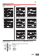
Relays with Plug-in or Soldered Terminals Relays with PCB Terminals
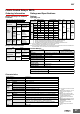
Ratings and Specifications
Ratings
Operating Coil
Note: 1. The rated current for AC is the value measured with a DC ammeter in half-wave rectification.
2. The rated current and coil resistance are measured at a coil temperature of 23°C with tolerances of +15%/−20% for the AC rated current and ±15% for the
DC coil resistance.
3. The AC coil resistance is a reference value only.
4. Operating characteristics were measured at a coil temperature of 23°C.
5. The maximum voltage capacity was measured at an ambient temperature of 23°C.
Contact Ratings
* With no icing or condensation.
Characteristics
Note:
The above values are initial values.
*1.
Measurement conditions: 1 A at 5 VDC using the voltage drop method
*2.
Measurement conditions: With rated operating power applied, not including contact bounce.
*3.
Measurement conditions: For 500 VDC applied to the same location as for dielectric strength
measurement.
*4.
Ambient temperature condition: 23° C
*5.
This value was measured at a switching frequency of 120 operations per minute.
Whenyourorder,specifytheratedvoltage.
Number of poles 2 poles
Classification Model Rated voltage (V)
Standard models MY2K
12 VAC
24 VAC
100 VAC
100/110 VAC
12 VDC
24 VDC
48 VDC
Number of poles 2 poles
Classification Model Rated voltage (V)
Standard models MY2K-02
24 VAC
100 VAC
12 VDC
24 VDC
Item
Set coil Reset coil
Set voltage
(V)
Reset
voltage (V)
Maximum
voltage (V)
Power consumption (VA, W)
Rated current (mA)
Coil
resistance (
Ω
)
Rated current (mA)
Coil
resistance (
Ω
)
Set coil Reset coil
Rated voltage (V)
50 Hz 60 Hz 50 Hz 60 Hz
AC
12 57 56 72 39 38.2 130
80% max. 80% max.
110% max. of
rated voltage
Approx. 0.6
to 0.9
(at 60 Hz)
Approx. 0.2
to 0.5
(at 60 Hz)
24 27.4 26.4 320 18.6 18.1 550
100 7.1 6.9 5,400 3.5 3.4 3,000
DC
12 110 110 50 235
Approx. 1.3 Approx. 0.6
24 52 470 25 940
48 27 1,800 16 3,000
Load
Item
Resistive load
Inductive load
(cos φ = 0.4, L/R = 7 ms)
Rated load
3 A at 220 VAC
3 A at 24 VDC
0.8 A at 220 VAC
1.5 A at 24 VDC
Rated carry
current
3 A
Maximum contact
voltage
250 VAC, 125 VDC
Maximum contact
current
3 A 3 A
Contact structure Single
Contact materials Au plating + Ag
Ambient operating
temperature
−55 to 60° C
*
Ambient operating
humidity
5% to 85%
Contact resistance
*
1
50 mΩ max.
Set
Time
*
2
AC: 30 ms max., DC: 15 ms max.
Minimum pulse width
AC: 60 ms, DC: 30 ms
Reset
Time
*
2
AC: 30 ms max., DC: 15 ms max.
Minimum pulse width
AC: 60 ms, DC: 30 ms
Maximum
operating
frequency
Mechanical
18,000 operations/h
Rated load
1,800 operations/h
Insulation resistance
*
3
100 MΩ
Dielectric
strength
Between coil
and contacts
1,500 VAC at 50/60 Hz for 1 min.
Between contacts of
different polarity
Between contacts of
the same polarity
1,000 VAC at 50/60 Hz for 1 min.
Between set/
reset coils
Vibration
resistance
Destruction
10 to 55 to 10 Hz, 0.5-mm single amplitude
(1.0-mm double amplitude)
Malfunction
10 to 55 to 10 Hz, 0.5-mm single amplitude
(1.0-mm double amplitude)
Shock
resistance
Destruction
1,000 m/s
2
Malfunction
200 m/s
2
Endurance
Mechanical
100,000,000 operations min.
(switching frequency: 18,000 operations/h)
Electrical
*
4
200,000 operations min.
(at 1,800 operations/hr, rated load)
Failure rate P value (reference value)
*
5
1 mA at 1 VDC
Weight
Approx. 30 g