
Datasheet


MY
28
Engineering Data
Engineering Data
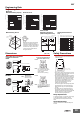
Dimensions (Unit: mm)
Safety Precautions
• For models with built-in operation indicators, check the coil polarity when
wiring and wire all connections correctly (DC operation).
• Use only combinations of OMRON Relays and Sockets.
• The UL and CSA certifications for this model are the same as for the MY4-
02.
Relay Replacement
To replace the Relay, turn OFF the power supply to the load and Relay coil
sides to prevent unintended operation and possible electrical shock.
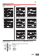
Maximum Switching Capacity Endurance Curve H
2
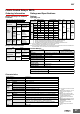
S Gas Data Malfunctioning Shock
MYQ4(Z) MYQ4 MYQ4
Energized
Y
X
Z
X’
Z’
Y’
550
400
600
300
550
600
400
600
600
250
600
700
Unit: m/s
2
Not energized
N = 20
Measurement: Shock was applied
3 times each in 6 directions along
3 axes with the Relay energized
and not energized to check the
shock values that cause the Relay
to malfunction.
Criteria: Non-energized: 200 m/s
2
Energized: 200 m/s
2
Shock
direction
DC inductive load
(L/R = 7 ms)
DC resistive load
AC resistive load
AC inductive load
(cos φ = 0.4)
10
0.01
0.03
0.05
0.07
0.1
0.5
0.3
0.7
1
3
7
5
15310 5030 100 500 1,000300
Contact voltage (V)
Contact current (A)
24 VDC resistive load
24 VDC inductive load (L/R = 7 ms)
220 VAC resistive load
220 VAC inductive load (cos φ = 0.4)
1
3
5
7
10
30
50
70
100
300
500
700
1,000
0 0.4 0.6 0.8 1.00.2 1.2
Contact current (A)
Number of operations (×10
4
operations)
Note: The durability of bifurcated
contacts is one-half that of
single contacts.
max.
N=10
min.
Measurements: Temperature: 40° C, Humidity: 60% to 70%,
H
2
S concentration: 5 ±3 ppm
The change in contact resistance was measured after
leaving the Relay in the above environment for a fixed
amount of time, then removing it to a constant-temperature
and constant-humidity environment for at least 30 minutes.
80
70
60
50
40
30
20
10
1
15310 5030 100 500 1,000300
Standing time (h)
Contact resistance (mΩ)
Note: 1. An AC model has coil disconnection self-
diagnosis.
2. For the DC models, check the coil polarity
when wiring and wire all connections
correctly.
MYQ4(Z)N
DC Models AC Models
Check the coil polarity when wiring
and wire all connections correctly.
(The coil has no polarity.)
Relays with Plug-in Terminals
or Soldered Terminals
MYQ4(Z)(N)
Relays with PCB Terminals
MYQ4(Z)-02
21.5 max.
28 max. 28.5 max.
0.5
4.1
0.6
2.6
1.0
35.5 max. 21.5 max.
3.75
Fourteen, 1.3-dia. holes
6.35
12.65
4.1
4.4
13.2
4.3
6.3
PCB Processing Dimensions
(Bottom View)
Terminal Arrangement/Internal
Connections (Bottom View)
Standard Models
Note:
The dimensional tolerance is ±0.1.
(The coil has no polarity.)
21.5 max.
28 max. 28 max.
6.4
2.6
Fourteen, 1.2-dia. × 2.2 oval holes
35.5 max. 21.5 max.