
Datasheet


19
MY
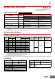
Characteristics
Note: These are initial values.
*1. Measurement conditions: 1 A at 5 VDC using the voltage drop method
*2. Measurement conditions: With rated operating power applied.
Ambient temperature condition: 23° C
*3. Measurement conditions: For 500 VDC applied to the same location as for dielectric strength measurement.
*4. Ambient temperature condition: 23° C
*5. This value was measured at a switching frequency of 120 operations per minute.
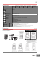
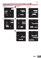
Dimensions (Unit: mm)
Item Number of poles 2 or 3 poles 4 poles
Contact resistance
*1
50 mΩ max.
Operation time
*2
20 ms max.
Release time
*2
20 ms max.
Maximum
operating
frequency
Mechanical 18,000 operations/h
Rated load 1,800 operations/h
Insulation resistance
*3
100 MΩ min.
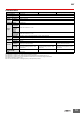
Dielectric
strength
Between coil and contacts
2,000 VAC at 50/60 Hz for 1 min.
Between contacts of
different polarity
Between contacts of the
same polarity
1,000 VAC at 50/60 Hz for 1 min.
Vibration
resistance
Destruction
10 to 55 to 10 Hz, 0.5-mm single amplitude
(1.0-mm double amplitude)
Malfunction
10 to 55 to 10 Hz, 0.5-mm single amplitude
(1.0-mm double amplitude)
Shock
resistance
Destruction 1,000 m/s
2
Malfunction 200 m/s
2
Endurance
Mechanical
AC: 50,000,000 operations min.
DC: 100,000,000 operations min.
(switching frequency: 18,000 operations/h)
Electrical
*4
500,000 operations min.
(rated load, switching
frequency: 1,800 operations/h)
200,000 operations min.
(rated load, switching
frequency: 1,800 operations/h)
Item Number of poles 2 or 3 poles 4 poles
Failure rate P value
(reference value)
1 mA at 5 VDC 1 mA at 1 VDC
Weight Approx. 35 g
4 poles, bifurcated contacts
The 1-pole, 2-pole, and 3-pole models
conform to these dimensions.
Fourteen, 1.2-dia. × 2.2 oval holes
2.6
2
0.5
0.5
6.4
36 max.
4.35
3.5
29 max.
38
44 max.
22.5 max.
Two, 3.5-dia. holes
or M3 screw holes
38
±0.2
Case-surface mounting
MY@F
Mounting Hole Dimensions
The above figure is for the MY4F. Note: Refer to the terminal arrangement and
internal connections diagrams for the MY2,
MY3, MY4, and MY4Z.