
Datasheet

3
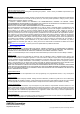
G7S-@-E
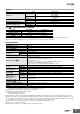
Dimensions (Unit: mm)
Relays with Forcibly Guided Contacts
Sockets
6 7
0.6
1.5
62 max.
58
10.8
22.5 max.
0.5
5 min.
37 max.
8
14.5
6
8
±
0.1
14.5
±
0.1
7
±
0.1
21
±
0.1
35
±
0.1
6
13 7
Fourteen,
1.8 dia.
24 VDC
13 14 33 34 51 52
23 24 41 42 61 62
0
1
+
−
24 VDC
13 14 33 34 51 52
23 24 43 44 61 62
0
1
+
−
G7S-4A2B-E
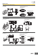
Mounting Hole Dimensions
G7S-3A3B-E
G7S-4A2B-E
G7S-3A3B-E
Terminal Arrangement/Internal
Connection Diagram
(Bottom View)
40 max.
33
±0.1
4
7.5
Fourteen, M3.0 × 8
Indicator
90.5 max.
5
(5)
5.9
3.1
80 max.
37
17
33
±0.1
Track-mounting Socket
P7S-14F-END
Mounting Hole Dimensions
Two, M3.5- or
4.0-dia. holes
Terminal Arrangement/Internal
Connection Diagram
(Top View)
520
1
51
61
62
34
33
13
14
23
24
4443
41
42
70.5 max.
23.5 max.
Two, 6.5 dia. × 8 depth
16.9
7
(15)
6
4.1
13.2
5×7=35
23.5 max.
14.5
8
57 max.
14.5
(21)
4.2
2.8
28
±0.2
28
±0.2
(16.9)
8
5×7=35
Two, 3.6 dia.
Fourteen, 2.5 dia.
6
7
Mounting Hole Dimensions
With G7S-3A3B-E mounted
Terminal
Arrangement/Internal
Connection Diagram
(Bottom View)
With G7S-4A2B-E mounted
Back-mounting Socket (PCB Terminals)
P7S-14P-E