
Datasheet

G7S-@-E
2
Contacts
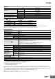
G7S-@-E Characteristics of Sockets
Note: Use the P7S-14F-END in the ambient humidity range of 25 to 85%, the P7SA-14P-E in the ambient humidity range of 5 to 85%.
* Measurement conditions: Measurement of the same points as for the dielectric strength at 500 VDC.
Characteristics
Note: 1. The above values are initial values.
2. Performance characteristics are based on a coil temparature of 23°C.
*1. Measurement conditions: 5 VDC, 10 mA, voltage drop method.
*2. Measurement conditions: Rated voltage operation
Ambient operating temperature: 23°C
Contact bounce time is not included.
*3. The insulation resistance was measured with a 500-VDC megohmmeter at the same locations as the dielectric strength was measured.
*4. When using a P7S Socket, the dielectric strength between coil and contacts and between different poles is 2,000 VAC, 50/60 Hz for 1 min.
*5. The coil refers to terminals 0-1, pole 1 refers to terminals 13−14, pole 2 refers to terminals 23−24, pole 3 refers to terminals 33−34, pole 4 refers
to terminals 41−42 or 43−44, pole 5 refers to terminals 51−52, and pole 6 refers to terminals 61−62.
*6. The durability is for an ambient temperature of 15 to 35°C and an ambient humidity of 25% to 75%.
*7. AC15: cosφ = 0.3, DC13: L/R = 96-ms
*8. The failure rate is based on an operating frequency of 60 operations/min.
Item Load Resistive load
Rated load
NO contact
10 A at 250 VAC
10 A at 30 VDC
NC contact
6 A at 250 VAC
6 A at 30 VDC
Rated carry current
NO contact 10 A
NC contact 6 A
Maximum switching voltage 250 VAC, 30 VDC
Maximum switching current
NO contact 10 A
NC contact 6 A
Model P7S-14F-END P7S-14P-E
C o n t i n u o u s c u r r e n t 10 A
Dielectric strength 2000 VAC for 1 min. between terminals
Insulation resistance 1000 MΩ min. *
Weight Approx. 110g Approx. 25g
Contact resistance *1 100 mΩ max.
Operating time *2 50 ms max.
Release time *2 50 ms max.
Must operate voltage 80% max.
Must release voltage 10% min.
Maximum operating
frequency
Mechanical 18,000 operations/h
Rated load 1,800 operations/h
Insulation resistance *3 100 MΩ min.
Dielectric strength *4 *5
Between coil and contacts:
Between coil and pole 3 or coil and pole 4: 4,000 VAC, 50/60 Hz for 1 min
Other than the above:2,500 VAC, 50/60 Hz for 1 min
Between different poles:
Between pole 1, 3, or 5 and pole 2, 4, or 6: 4,000 VAC, 50/60 Hz for 1 min
Other than the above:2,500 VAC, 50/60 Hz for 1 min
Between contacts of same polarity:1,500 VAC, 50/60 Hz for 1 min
Vibration
resistance
Destruction 10 to 55 to 10 Hz, 0.75-mm single amplitude (1.5-mm double amplitude)
Malfunction 10 to 55 to 10 Hz, 0.375-mm single amplitude (0.75-mm double amplitude)
Shock resistance
Destruction 1,000 m/s
2
Malfunction 100 m/s
2
Durability *6
Mechanical 10,000,000 operations min. (at approx. 18,000 operations/h)
Electrical 100,000 operations min. (at the rated load and approx. 1,800 operations/h)
Inductive load
switching capability *7
(IEC60947-5-1)
NO Contact
AC15 AC240V 5A
DC13 DC24V 2A
NC Contact
AC15 AC240V 3A
DC13 DC24V 2A
Failure rate (P level)
(reference value *8)
5 VDC, 1 mA
Ambient operating temperature –25 to 70°C (with no icing or condensation)
Ambient operating humidity 5% to 85%
Weight Approx. 65 g