
Datasheet

K8AK-PA
8
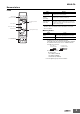
Checking Operation
With the rated input voltage applied, gradually change the
voltage to any one phase. The Unit will operate when the
difference between the maximum and minimum voltage
phases reaches or exceeds the asymmetry operating value.
Asymmetry operating value = Rated input voltage ×
Asymmetry set value (%)
Example: For monitoring mode set to three-phase three-wire
monitoring, a rated voltage of 200 V, and an operating time
of 5 s.
Note: K8AK-PA@ output relays are normally operative.
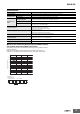
Connection Diagram 1
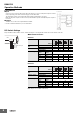
How to Measure the Operating Time
Operating Time
Adjust the slide resistor so that the voltage difference applied
to the K8AK terminals is equal to or greater than the
asymmetry operating value when the auxiliary relay operates,
as shown in connection diagram 2. Close the switch and use
the cycle counter to measure the operating time.
Connection Diagram 2
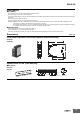
Checking the Phase Sequence and Phase Loss Operation
Phase Sequence Operation
Switch the wiring, as shown by the dotted lines in connection
diagram 1, to reverse the phase sequence and check that the
K8AK operates.
Phase Loss Operation
Create a phase loss for any input phase and check that the
K8AK operates.
Load-side Phase Loss
In principle, phase loss cannot be detected on the load side
because the K8AK-PA@ measures three-phase voltage to
determine phase loss.
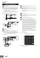
Motor Load Phase Loss during Operation
Phase loss cannot be detected for motor loads during
operation. Use the asymmetry detection function.
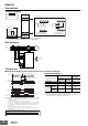
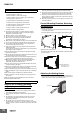
Normally, three-phase motors will continue to rotate even if
one phase is open. The three-phase voltage will be induced
at the motor terminals. The diagram shows voltage induction
at the motor terminals when phase R is lost with a load
applied to a three-phase motor. The horizontal axis shows the
motor load as a percentage of the rated load, and the vertical
axis shows voltage as a percentage of the rated voltage. The
lines in the graph show the voltage induced at the motor
terminals for each load when phase loss occurs during
operation. As the graph shows, phase loss cannot be
detected because the motor terminal voltage does not drop
very much even if a phase is lost when the load on the motor
is light. Use the asymmetry detection function to detect
asymmetry in the motor terminal voltages.
Set the operating time carefully because it will affect the time
from when the phase loss occurs until tripping when this
function is used.
Characteristic Curve Diagram
Note: For phase loss of phase R. V
ST
, V
TR
, and V
RS
indicate the motor
terminal voltage at phase loss.
Questions and Answers
Q
Alarm indicator
Asymmetry operating voltage (set value)
Contact
T1: Power ON lock time (1 s or 5 s)
Flashing
L1
L2
L3
T
T: Operating time (0.1 to 30 s)
Lit
Inputs
0 to 150 V
V1
Three-phase variable
autotransformer
L1
L2
L3
3φ
200 VAC
V2 V3
L1
L2
Q
3φ 200 VAC
L1
L2
L3
±
C 200 V
Cycle counter
V1
V2 V3
X
X/a
X/b
L1
L2
L3
R1
R2
R1: Slide resistor
200 Ω 200 W
R2: 100 Ω 400 W
Q
Q
Q
100
95
90
85
80
75
70
65
60
55
50
45
100 2030405060708090100
110
V
ST
V
TR
V
RS
This characteristic curve
shows the approximate values
only.
Note:
Voltage (as a percentage of rated voltage)
Motor load (as a percentage of rated load)