
Datasheet

K8AK-PA
5
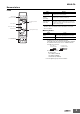
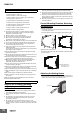
Nomenclature
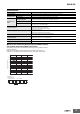
Front
●Indicators
* The input across L1 and L2 is used for the internal power supply.
Therefore, the power indicator will not be lit if there is no input
across L1 and L2.
●Setting Knobs
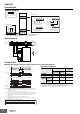
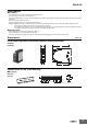
Note: 1. Use either a solid wire of 2.5 mm
2
maximum or a ferrule with
insulating sleeve for the terminal connection.
The length of the exposed current-carrying part inserted into
the terminal must be 8 mm or less to maintain dielectric
strength after connection.
Recommended ferrules
Phoenix Contact
• Al 1,5-8BK (for AWG16)
• Al 1-8RD (for AWG18)
• Al 0,75-8GY (for AWG18)
2. Screw tightening torque: 0.49 to 0.59 N·m
Power indicator
Terminal block
(See notes 1 and 2.)
Relay status indicator
Terminal block
(See notes 1 and 2.)
Asymmetry rate knob
(ASY.)
Operating time knob (T)
Alarm indicator
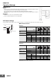
Item Meaning
Power indicator
(PWR: Green)
Lit when power is being supplied*
Relay status
indicator
(RY: Yellow)
Lit when relay is operating (normally lit).
Alarm indicator
(ALM: Red)
Asymmetry voltage error indicator
The indicator flashes to indicate the error status after
the input has exceeded the set value while the operat-
ing time is being clocked.
Item Usage
Asymmetry rate knob
(ASY.)
Used to set the asymmetry rate to 2% to 22%.
Operating time knob (T)
Used to set the operating time to 0.1 to 30 s.
For 2.5 mm
2
or
smaller solid wires
For ferrules with
an insulation sleeve.
8 mm max. 8 mm max.