
Datasheet

K8AK-PA
4
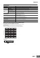
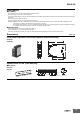
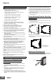
Connections
Terminal Diagram
Note: 1. Do not connect anything to terminals that are shaded in gray.
2. Use the recommended ferrules if you use twisted wires.
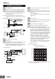
Wiring Example
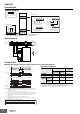
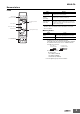
Timing Charts
●Voltage Asymmetry and Phase Sequence/Phase Loss Operation Diagram
Operation Indicators
*1 L1 and L2 are also used for the power supply. If the voltage
becomes very low, the indicator will turn OFF.
*2 The indicator will flash once per second after an incorrect phase is detected
and once per 0.5 second during the detection time.
L1
L2
L3
11 12
Relay output
250 VAC, 5 A (resistive load)
3-phase,
3-wire
power
supply
30 VDC, 5 A (resistive load)
14
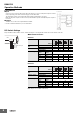
Input Voltages
Monitoring 3-phase,
3-wire Power Supply
Monitoring 3-phase,
4-wire Power Supply
or
3-phase,
4-wire
power
supply
Control Output
N
_
_
L1
L2
L3
__N
__N
L1
L2
L3
Relay Output
11 12 14
L1 L2 L3
11 12
14
N_
_
L1
L2
L3
N
3-phase
voltage
Motor
Power supply
AC/DC
L2
Relay
Asymmetry operation voltage (set value)
Input
Alarm indicator
Input
Relay 11-14
Alarm indicator
L1
L3
L2
L3
L2
L1
L1
L2
L3
L2
L1
L3
t
t1
L1
L2
L3
L1
L3
Flashing
Lit
t: Operating time (0.1 to 30 s)
t1: Power ON lock (1 s or 5 s)
Phase loss operation
Phase sequence operation
Note: 1. K8AK-PA@ output relay is normally operative.
2. The power ON lock prevents unnecessary alarms from being generated during
the instable period when the power is first turned on. There is no relay output
during timer operation.
3. Phase loss is detected by L1, L2, and L3 voltage drops.
A phase loss will exist if any of the phases drops below 60% of the rated input.
4. L1 and L2 function both as the power supply terminals and as input terminals.
If the voltage drops dramatically, then the Relay will not operate due to an
undervoltage.
5. Motor load phase loss cannot be detected during operation.
6. Phase loss is detected based on voltage, so phase loss cannot be detected on
the load side.
Flashing Flashing
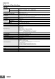
Calculating the Asymmetry Operating Voltage
Asymmetry operation condition = (Highest voltage − Lowest voltage) > Asymmetry operating voltage
Asymmetry operating voltage = Rated input voltage (V) × Asymmetry set value (%)
Note: The rated input voltage is selected and set with the DIP switch.
Flashing
Delay: 250 ms (reference value)
Hysteresis: Fixed at 5%
Item
Display
Contact
operation
Ry
indicator
Alarm
indicator
Alarm relay
Asymmetry OFF ON OFF
Phase loss OFF ON
*1
OFF
Phase
sequence
Incorrect
phase
OFF Flashing
*2
OFF
Correct
phase
ON OFF ON