
User Manual

K7L-AT50@/AT50D@@
9
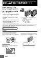
(TOP VIEW)
Terminal
Arrangement
2
4 dia.
9.5
35.5
19.5
30 max.
54 max.
7
Eight, M3.5 x 8
19.5
max.
71.5
max.
31.5
4
2
1
7
8
3
4
6
5
73
max.
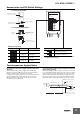
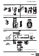
Track-mounted Sockets *
P2RF-08 (Round terminals can be used.)
Note:
Secure the Sockets with M3 screws at a torque of 0.78 to 1.18 N
m.
*
The applicable models of the K7L depend on the model of the Socket. If
the correct Socket is not used, the K7L nameplate will be upside down.
16
4
85.5
max.
3.5 dia. hole
2
1.5
M3 screws
1
8
4
2
3
5
7
6
(A2)
(A1)
(24) (14)
(12)(22)
(11)(21)
Figures in parentheses
indicate DIN standard
numbers.
11.5
61 max.
35.5
39.5
3 dia.
2
48 max.
84 max.
(Including height of DIN track)
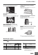
(TOP VIEW)
Terminal Arrangement
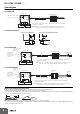
Track-mounted Sockets *
P2RF-08-E
Note:
Secure the Sockets with M3 screws at a torque of 0.78 to 1.18 N
m.
*
The applicable models of the K7L depend on the model of the Socket. If
the correct Socket is not used, the K7L nameplate will be upside down.
27.6
28.1
45
36.3
27.6
35.5
27.25
52.1
83 max.
52.4
3.9
56.5 max.
15.5 max.
(3)
(3)
90 max.
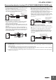
Terminal Arrangement/
Internal Connection Diagram
(TOP VIEW)
56.3
14
22
24
21
12
11
A1A2
(8)(1)
(2) (7)
(4) (5)
(3) (6)
Track-mounted Sockets
P2RF-08-PU
Note:
The applicable models of the K7L depend on the model of the Socket. If the correct
Socket is not used, the K7L nameplate will be upside down.
Note: The numbers in parentheses
are traditionally used
terminal numbers.
10
8
2
32 dia.
5.5 dia.
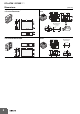
Overall length
2,000 mm
2.6-dia. vinyl-insulated round cable
with 2 conductors
Conductor cross section:
0.079 mm
2
Sheath: Fluoroplastic, 0.66 dia.
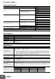
Electrode
Liquid Leakage Point Sensor
F03-16PS
F03-16PS-F
Bottom View
19.2
3
8.85
10
1222.5
6 dia.
R3
24
1
R5
1
Glued surface *
Point Sensor Mounting Bracket
F03-26PS
* Use a commercially available bonding agent for PVC.
Do not use adhesive tape for securing.