
User Manual

K7L-AT50@/AT50D@@
6
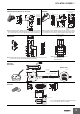
Connections
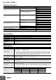
External Connections
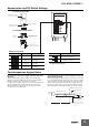
K7L-AT50/AT50B
Connection Examples
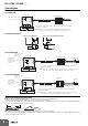
K7L-AT50D/AT50DB
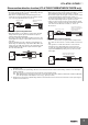
K7L-AT50DP/AT50DPB
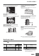
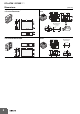
Stripping and Connecting Terminals
1. Cut into the Sensing Band approximately 4 to 6 cm in from the end as shown in the diagram below.
2. Strip away approximately the last 9 mm of the sheath to expose the core (SUS line).
3. To connect to the Terminal Block, push down the top of the terminal with a screwdriver* and insert the core from the side. More Sensing Bands
can be connected simply by wiring in an arch shape.
Note: When you are finished working, sufficiently confirm that there is an electrical connection.
* You can use a commercially available screwdriver, but we recommend either 1) a 210-350/01 Screwdriver or 2) a 209-132 Operating Tool from
Wago. Information: //www.wago.com
234
423
5
6
7
8
1
2
3
4
* Use a class 2 power supply for the DC power supply if UL/CSA or CE Marking
compliance is required.
Note: Always use a 3-conductor cable for wiring and connect to terminals 2, 3,
and 4 on the Unit. Connect the Sensing Band between terminals 2 and 4.
(Bottom view)
12 to 24 VDC *
Connecting cable
(0.2 mm
2
min.)
F03-20 Terminal Block
Sensing Band
OUT+ Open-collector output
OUT- 100 mA at 30 VDC max.
Signal
transmission
Level input 1
Level input 2
Load
Load
Load power supply Load power supply
+
6
5
+
6
5
Connection as an NPN Output Connection as an PNP (Equivalent) Output
234
423
5
6
7
8
4
3
2
1
+
-
(4-2)
2-4
Connecting cable
(0.2 mm
2
min.)
F03-20 Terminal Block
Sensing Band
F03-20T Terminator
Open-collector output
100 mA at
30 VDC max.
(Bottom view)
Liquid leakage
detection output
Disconnection
detection output
Common
OUT+
BURN OUT+
COM-
Signal
transmission
Level input 1
Level input 2
12 to 24 VDC *
* Use a class 2 power supply for the DC power supply if UL/CSA or CE Marking
compliance is required.
Note: Always use a 3-conductor cable for wiring and connect to terminals 2, 3, and 4
on the Unit. Connect the Sensing Band between terminals 2 and 4.
8
234
423
5
6
7
4
3
2
1
(4-2)
2-4
(Bottom View)
Signal
transmission
Level input 1
Level input 2
Liquid leakage
detection output
Disconnection
detection output
Common
OUT-
BURN OUT-
COM+
12 to 24 VDC
Commercially available
connecting cable (0.2 mm
2
min.)
Terminal Block
F03-20
Sensing Band
Example: F03-16PE
Terminator
F03-20T
Open-collector output
30 VDC max.
100 mA
* Use a class 2 power supply for the DC power supply if UL/CSA or CE Marking
compliance is required.
Note: Always use a 3-conductor cable for wiring and connect to terminals 2, 3, and 4
on the Unit. Connect the Sensing Band between terminals 2 and 4.
9 mm
Exposed
part of
core
Insert
F03-20
Terminal
Block
4 to 6 cm