
User Manual
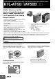

K7L-AT50@/AT50D@@
4
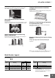
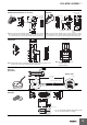
Ordering Information
*1. Accessories are provided. Check the accessories listed in the specifications for details.
*2. The applicable models of the K7L depend on the model of the Socket. If the correct Socket is not used, the K7L nameplate will be upside down.
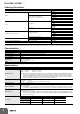
Characteristics
Specifications
* For the K7L-AT50D@@.
Product name Model
Amplifier
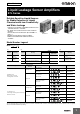
Liquid Leakage Sensor Amplifier *1
K7L-AT50
K7L-AT50B
Liquid Leakage Sensor Amplifier
with Disconnection Detection Function *1
K7L-AT50D
K7L-AT50DP
K7L-AT50DB
K7L-AT50DPB
Sensors
Sensing Band
F03-15
F03-16PE
F03-16PT
F03-16SF
F03-16SFC
Point Sensor
(for K7L-AT50/AT50B)
F03-16PS
F03-16PS-F
Mounting Brackets and Stickers
Sensing Band Stickers
F03-25
F03-26PES
F03-26PEN
F03-26PTN
Point Sensor Mounting Brackets F03-26PS
Socket *2 (for K7L-AT50/AT50D)
Round terminals can be used. P2RF-08
Round terminals cannot be used. P2RF-08-E
Socket *2 (for K7L-AT50B/AT50DB) Push-In Plus Terminal P2RF-08-PU
Terminal Block F03-20
Ambient temperature Operating: –10 to +55°C
Ambient humidity Operating: 45% to 85%
Insulation resistance 10 M at 100 VDC between case and current-carrying parts
Dielectric strength 1,000 VAC at 50/60 Hz for 1 min between case and current-carrying parts
Power consumption
1 W max.
Response time
Operate: 800 ms max.
Release: 800 ms max.
When turning ON power: 2 s max.
Weight Approx. 14 g
Rated power supply voltage 12 to 24 VDC (Allowable voltage fluctuation range: 10 to 30 VDC)
Operate resistance
0 to 50 M, variable
Range 0: 0 to 250 k. Range 1: 0 to 600 k
Range 2: 0 to 5 k
. Range 3: 0 to 50 k
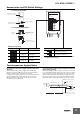
Note: The range is set using the DIP switch on the side of the Sensor Amplifier. (Refer to DIP Switch Settings.)
Set the corresponding pin of the DIP switch in the up position. (For range 0, set all 3 pins in the down
position.) The adjuster (ADJUST) on the top of the Sensor Amplifier sets the resistance value for detection
within the set range. It is factory-set to the upper limit. (Normally, the K7L can be used with the adjuster
at this setting.) With any range, resistance values can be set from 0 .
Disconnection detection function
*
Detection signal: 10 VDC max., 200 ms
Detection time: 10 s max.
Recovery: Operation is recovered by resetting the power supply.
Release resistance 105% min. of operate resistance
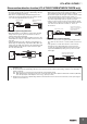
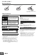
Output configuration
Open-collector transistor output with 100 mA at 30 VDC max. for both liquid leakage detection and disconnection detection.
Max. 30 VDC, 100mA
Note:
If the rightmost pin of the DIP switch on the side of the Sensor Amplifier is set to the down position, the output
turns ON when liquid is detected; if it is set to the up position, the output turns OFF when liquid is detected.
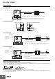
Wiring distance
Connecting cable: 50 m max.
Sensing Band length: 10 m max.
Note:
These values are possible on condition that a completely insulated 3-conductor VCT cable with a thickness of 0.75
mm
2
and a dielectric strength of 600 V is used together with a Liquid Sensing Band specified by OMRON. (A 0.2-mm
2
cable can also be used.)
Accessories
Terminal Block Screwdriver for ADJUST Terminator
K7L-AT50/AT50B 1 1 ---
K7L-AT50D/AT50DB/
AT50DP/AT50DPB
111
K7L-AT50D-S 1 1 ---