
User Manual


F03-16PE/-16PT/-15/-16PS
23
Connecting the Sensing Band
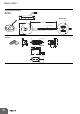
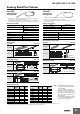
Connecting F03-20 Terminal Blocks and Sensing Cables
The F03-20 Terminal Block is provided to connect the connecting
cable from the K7L Liquid Leakage Sensor Amplifier to a Sensing
Band in a liquid detection application.
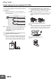
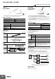
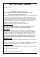
Stripping and Connecting Terminals
1. Cut into the Sensing Band approximately 4 to 6 cm in from the end
as shown in the diagram below.
2. Strip away approximately the last 9 mm of the sheath to expose
the core (SUS line).
3. To connect to the Terminal Block, insert the screwdriver * from the
top of the Terminal Block and insert the stripped end of the core
from the side. (Refer to Dimensions on page 17.)
Note: Check that the wiring is secure before using the K7L in
applications.
* You can use a commercially available screwdriver, but we
recommend either 1) a 210-350/01 Screwdriver or 2) a 209-132
Operating Tool from Wago. Information: //www.wago.com
The F03-20 Terminal Block was designed to maintain continuity
between the connecting cable and Sensing Band. The tensile
strength after connection to the Sensing Band was not considered. If
the Sensing Band may be pulled, use F03-26PES Sensing Band
Stickers to secure it. If it is located where people may step on it, attach
a commercially available cover to take other measures to ensure that
the Sensing Band connected to a Terminal Block is not subjected to
external force.
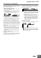
Application Examples in Which an F03-16PE Sensing Band Is More
Difficult to Pull Free from an F03-20 Terminal Block
• Fold the electrode section of the Sensing Band to double the
electrode plate thickness and insert it into the Terminal Block.
• Attach round crimp terminals on the electrode section of the
Sensing Band and connect them to a commercially available
terminal block.
If required by your application, another method can be used (e.g.,
installation with suitable connectors).
After installation, confirm that a reliable electrical connection has
been achieved.
Also, when you remove a Sensing Band from an F03-20 Terminal
Block, do not pull it with excessive force. Remove it while inserting a
screwdriver from the top of the Terminal Block.
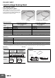
Interval Between Stickers
When securing the Sensing Band with Stickers, attach the Stickers at
intervals of 20 to 30 cm in places where the core is not exposed.
Note: 1. When using the F03-26PES (adhesive-tape model), be sure
to wipe all moisture, oil, and dust from the surface to which
the Sticker is to be attached. Failure to do so may result in
insufficient adhesion, and the Sticker may peel away from
the surface.
2. When using the F03-26PEN (screw model), before
installing the Sensing Band, it is necessary to perform stud
welding. For details on the pitch of the studs, refer to the
information on the dimensions of Sensing Band Stickers.
3. If you connect a Sensor Band with an F03-20 Terminal
Block and F03-20T Terminator, secure the Sensing Band
with Sensing Stickers near the Terminal Block and
Terminator to help adsorb stress, e.g., from something
pulling on the Sensing Band.
Bending the Sensing Band
To change the direction of the Sensing Band, bend the Sensing Band
in one or two places where the core is not exposed.
4 to 6 cm
9 mm
Exposed
part of
core
Insert
F03-20
Terminal
Block
SecuretheSensingBandasclosetoa
TerminalBlockorTerminatoraspossible.
TerminalBlockorTerminator
Sensing
Band
Sticker
20 to 30 cm
Bent in 2 places
Bent in 1 place
Note: Bend the Sensing Band approximately 4 cm (i.e., twice the
distance between places where the core is exposed) away
from places where a Sticker is attached. If the Sensing Band
is bent at places further away than this, the Sensing Band may
come away from the surface.