
Datasheet


H3DK-M/H3DK-S
7
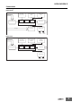
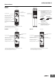
Nomenclature
*If the switch is left between settings, proper operation may not be possible.
Make sure that the switch is set properly.
Note: The default settings are for 0.1 s in mode A.
Terminal Block
(See notes 1 and 2.)
Bottom ViewFront View
Time range switch
Operating mode switch
Output indicator (orange)
(Lit while Timer gives output.)
Operation/power indicator (green)
(Lit while the power is ON.)
INIT/TIME switch for relay R2
(Default setting is for time-limit
output.)*
Main dial (for
setting the time)
User label
attachment location
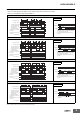
Note 1. Use solid wire (2.5 mm
2
max.) or fer-
rules with insulative sleeves to connect
to the terminals.
To maintain the withstand voltage after
connecting the terminals, insert no
more than 8 mm of exposed conductor
into the terminal.
Recommended Ferrules
Phoenix Contact
•AI@@@ Series
•AI-TWIN@@@ Series
Note 2. Screw Tightening Torque
Recommended torque: 0.49 N·m
Maximum torque: 0.98 N·m
8 mm max. 8 mm max.
Using Solid Wire
(2.5 mm
2
Max.)
Using Ferrule with
Insulative Sleeve
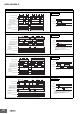
H3DK-M2
H3DK-S2
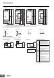
User label attachment
location
Main dial
(for setting the time)
Front View
Time range switch
Output indicator (orange)
(Lit while Timer gives output.)
Operation/power indicator (green)
(Lit while the power is ON.)
Operating mode switch
*If the switch is left between settings, proper operation may not be possible.
Make sure that the switch is set properly.
Note: The default settings are for 0.1 s in mode A.
User label attachment
location
Main dial
(for setting the time)
Front View
Time range switch*
Output indicator (orange)
(Lit while Timer gives output.)
Operation/power indicator (green)
(Lit while the power is ON.)
Operating mode switch*
*If the switch is left between settings, proper operation may not be possible.
Make sure that the switch is set properly.
Note: The default settings are for 0.1 s in mode A.
H3DK-M1
H3DK-S1