
Datasheet


H3DK-M/H3DK-S
6
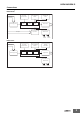
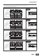
■ Terminal Arrangement
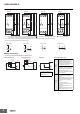
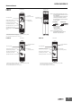
■ Input Connections
The start input of the H3DK-M1/-M2 is a voltage input.
A1 15
B1
A2
18
16
A1 15
25/21
B1
26/2228/24
A2
18
16
A1 15
25/21
26/2228/24
A2
18
16
A1 15
A2
18
16
15
R1
1618
15
R1
1618
25/21
R2
*
26/2228/24
15
R1
1618
15
R1
1618
25/21
R2
*
26/2228/24
H3DK-M1 H3DK-M2 H3DK-S1 H3DK-S2
Start
See note 3.
(DIN notation) (DIN notation) (DIN notation) (DIN notation)
Start
See note 3. See note 3. See note 3.
A2
A1
15
1816
B1
A2
A1
15
1816
B1
(21)
25
28
(24)
26
(22)
A2
A1
15
1816
A2
A1
15
1816
(21)
25
28
(24)
26
(22)
Note 1: The time-limit contact symbol for previous models of Timers was . The time-limit contact symbol for the H3DK is . A different symbol is
used because the H3DK supports multiple operating modes.
Note 2: *The relay R2 can be set to either instantaneous or time-limit contacts using the switch on the front of the Timer.
Note 3: The power supply terminals do not have polarity.
Sensor
Timer
A1 (+)
A2 (−)
B1
Start
24
VDC
24 VDC
(sensor
power supply)
(+)
(−)
Sensor
Timer
A1 (−)
A2 (+)
B1
Start
24
VDC
(−)
(+)
Timer
A1
A2
B1
Start
Operates when PNP transistor turns ON. Operates when NPN transistor turns ON. Operates when relay turns ON.
24 VDC
(sensor
power supply)
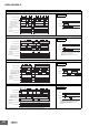
Voltage Input Signal Levels
Tran-
sistor
input
1. Transistor ON
• Residual voltage: 1 V max.
Voltage between terminals B1
and A2 must be equal to or
higher than the rated high level
voltage (20.4 VDC min.).
2. Transistor OFF
• Leakage current: 0.01 mA max.
Voltage between terminals B1
and A2 must be equal to or
below the rated low level voltage
(2.4 VDC min.).
Relay
input
Use relays that can adequately
switch 0.1 mA at the imposed
voltage.
When the relay is ON or OFF, the
voltage between terminals B1 and
A2 must be within the following
ranges:
• 24 to 240 VAC/DC
When relay is ON: 20.4 to 264
VAC/DC
When relay is OFF: 0 to 2.4 V
• 12 VDC
When relay is ON: 10.8 to 13.2 V
When relay is OFF: 0 to 1.2 V
PNP Transistor Input NPN Transistor Input Relay Input
Consider the minimum load
of the relay. (See signal
levels on the right.)