
Datasheet

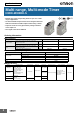

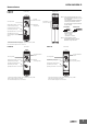


H3DK-M/H3DK-S
3
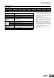
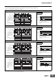
Specifications
■ Time Ranges
■ Ratings
Time range setting 0.1 s 1 s 10 s 1 min 10 min 1 h 10 h 100 h
Set time range 0.1 to 1.2 s 1 to 12 s 10 to 120 s 1 to 12 min 10 to 120 min 1 to 12 h 10 to 120 h 100 to 1,200 h
Scale numbers 12
Power supply voltage
*1
• 24 to 240 VAC/DC, 50/60 Hz
*2
• 12 VDC
*2
Allowable voltage fluctuation
range
• 24 to 240 VAC/DC: 85% to 110% of rated voltage
• 12 VDC: 90% to 110% of rated voltage
Power reset Minimum power-OFF time: 0.1 s
Reset voltage 10% of rated voltage
Voltage input
• 24 to 240 VAC/DC
High level: 20.4 to 264 VAC/DC, Low level: 0 to 2.4 VAC/DC
• 12 VDC
High level: 10.8 to 13.2 VDC, Low level: 0 to 1.2 VDC
*3
Power con-
sumption
H3DK-M2/-S2 At 240 VAC: 6.6 VA max.
*4
H3DK-M1/-S1 At 240 VAC: 4.5 VA max.
*4
H3DK-M2A/-S2A At 12 VDC: 0.9 W max.
H3DK-M1A/-S1A At 12 VDC: 0.6 W max.
Control output
Contact output, 5 A at 250 VAC with resistive load (cosφ = 1),
5 A at 30 VDC with resistive load
*4, *5
Ambient operating temperature −20 to 55°C (with no icing)
Storage temperature −40 to 70°C (with no icing)
Ambient operating humidity 25% to 85%
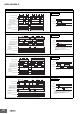
*1. When using a 24-VDC power supply voltage, there will
be an inrush current of approximately 0.25 A. Allow fo
r
this inrush current when turning ON and OFF the
power supply to the Timer with device with a solid-
state output, such as a sensor.
*2. DC ripple: 20% max.
*3. The power consumption is for mode A after the Time
r
times out.
For the H3DK-M@, the maximum power consumption
is given, including the current consumed by the input
circuit.
*4. Refer to DC Power Consumptions (Reference Infor
-
mation) on page 27 for DC power consumptions.
*5. The control output ratings are for one H3DK operating
alone. If you operate two or more Timers side by side,
refer to Installation Pitch and Output Switching Capac
-
ity (Reference Values) on the next page.
*6. 125 VDC: 0.15 A max. with resistive load, 125 VDC:
0.1 A with L/R of 7 ms.
Minimum load: 10 mA at 5 VDC (P level, reference
value)