
Datasheet


H3DK
26
● Changing Switch Settings
Do not change the time unit, time scale, operating mode, or INIT/
TIME switch while the Timer is in operation. Doing so may result
in malfunction. Turn OFF the power supply before changing the
setting of any switch.
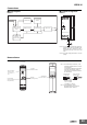
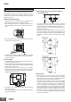
● Mounting and Dismounting
• Although there are no particular mounting restrictions, the
Timer should be mounted as horizontally as possible.
• When mounting the Timer on a mounting Track, loosen the
two hooks, press the Timer onto the Track, and then insert the
hooks.
• When removing the Timer, pull out the two hooks, and then
remove the Timer from the Track
• It will be easier to mount and dismount the Timer if a distance
of 30 mm or more is provided between the bottom of the Timer
and other equipment.
● Power Supply
• The power supply can be connected to the power input termi-
nals without considering polarity.
• A DC power supply can be connected if its ripple factor is 20%
or less and the average voltage is within the allowable voltage
fluctuation range of the Timer.
• For the power supply of the input device, use an isolating
transformer in which the primary and secondary windings are
mutually isolated and the secondary winding is not grounded.
(H3DK-M1 and H3DK-M2 only)
• The H3DK-H has a large inrush current. Provide sufficient
power supply capacity.
If the power supply capacity is too small, there may be delays
in turning ON the output.
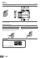
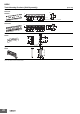
● Relationship between Input and Power Supply Cir-
cuits (H3DK-M1/-M2)
• The input circuit and the power supply circuit are configured
independently. The input circuit can be turned ON and OFF
without considering the ON/OFF state of the power supply.
A voltage equivalent to the power supply voltage is also
applied to the input circuit.
• If a relay or transistor is connected to two or more Timers, the
input terminals of those Timers must be wired properly so that
they will not be different in phase or the terminals will be short-
circuited to one another. Always use the same power supply
phases.
● Environment
• When using the Timer in an area with excessive electronic
noise, separate the Timer and input device as far as possible
from the noise sources. It is also recommended to shield the
input signal wiring to prevent electronic interference.
• The external impulse voltage entering across the power supply
terminals has been checked against a ±1.2×50 µs standard
waveform according to JEC-210, Impulse Voltage/Current
Test, of The Institute of Electrical Engineers of Japan. Surge
or noise superimposed on the power supply may damage
internal components or cause them to malfunction. We recom-
mend that you check the circuit waveform and use surge
absorbers. The effects on components depend on the type of
surge and noise that are generated. Always perform testing
with the actual equipment.
Precautions for Correct Use
Hook
Hook
30 mm min.
Hook
Hook
A1
B1
A2
Circuit
Power
H3DK
Isolation transformer is required.
Rectifier circuit
Start
input
Input circuit
Power supply circuit
B1 A1
A2
AC/DC
power supply
H3DK
H3DK
Power
B1
A1
A2
A1
A2
B1
H3DK
H3DK
Power
B1
A1
A2
A1
A2
B1
Contact or transistor for
external input signal
Contact or transistor for
external input signal