
Datasheet


H3DK-H
23
Connections
Nomenclature
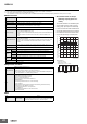
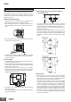
■ Block Diagrams
H3DK-H
Output circuitCounting circuitOscillation circuit
Indicator circuit
AC (DC) input
Power supply
circuit
Time specification
switches
Power
interruption
detection circuit
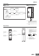
■ Terminal Arrangement
H3DK-H
Note 1: The above figure shows the terminal ar-
rangement for a 24 to 48-VAC/DC model.
Models with 100 to 120-VAC or 200 to
240-VAC power input do not have a DC
input.
Note 2: The power supply terminals do not have
polarity.
A1 15
A2
18
16
15
R1
1618
A2
A1
15
1816
(DIN notation)
Terminal block
(See notes 1 and 2.)
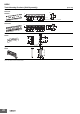
Bottom View
Main dial
(for setting the time)
Front View
Time range switch
(S Series: ×0.1 or
×1, L Series: ×1 or
×10)
Power indicator
(green) (Lit while
the power is ON.)
User label
attachment location
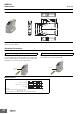
H3DK-H
Note 1. Use solid wire (2.5 mm
2
max.) or fer-
rules with insulative sleeves to connect
to the terminals.
To maintain the withstand voltage after
connecting the terminals, insert no
more than 8 mm of exposed conductor
into the terminal.
Recommended Ferrules
Phoenix Contact
•AI@@@ Series
•AI-TWIN@@@ Series
Note 2. Screw Tightening Torque
Recommended torque: 0.49 N·m
Maximum torque: 0.98 N·m
8 mm max. 8 mm max.
Using Solid Wire
(2.5 mm
2
Max.)
Using Ferrule with
Insulative Sleeve