
Datasheet


H3DK-F
13
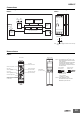
Connections
Nomenclature
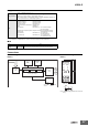
■ Block Diagrams
H3DK-F
AC (DC)
input
ON
indicator
OFF
indicator
One-chip microcomputer
Output circuit
Indicator
circuit
RAMROM Clock
ON/OFF start switch
Power supply
circuit
Time
specification
switches
ON/OFF time setting
detection circuit
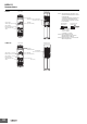
■ Terminal Arrangement
H3DK-F
Note: The power supply terminals do not have po-
larity.
A1 15
A2
18
16
15
R1
1618
A2
A1
15
1816
(DIN notation)
Terminal Block
(See notes 1 and 2.)
ON time range switch
Bottom ViewFront View
ON time setting dial
(Sets the ON time.)
OFF time setting dial
(Sets the OFF time.)
ON output
indicator (orange)
OFF output
indicator (green)
OFF time range switch
ON/OFF start switch
(Default setting is for
an OFF start.)
User label
attachment location
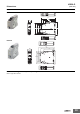
H3DK-F
Note 1. Use solid wire (2.5 mm
2
max.) or fer-
rules with insulative sleeves to connect
to the terminals.
To maintain the withstand voltage after
connecting the terminals, insert no
more than 8 mm of exposed conductor
into the terminal.
Recommended Ferrules
Phoenix Contact
•AI@@@ Series
•AI-TWIN@@@ Series
Note 2. Screw Tightening Torque
Recommended torque: 0.49 N·m
Maximum torque: 0.98 N·m
8 mm max. 8 mm max.
Using Solid Wire
(2.5 mm
2
Max.)
Using Ferrule with
Insulative Sleeve