
Datasheet


H3DK-F
12
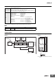
*1. When using a 24-VDC power supply voltage, there will be an inrush current of approximately 0.25 A. Allow for this inrush current when turning ON and OFF the
power supply to the Timer with device with a solid-state output, such as a sensor.
*2. DC ripple: 20% max.
*3. Refer to DC Power Consumptions (Reference Information) on page 27 for DC power consumptions.
*4. The control output ratings are for one H3DK operating alone. If you operate two or more Timers side by side, refer to Installation Pitch and Output Switching Capacity
(Reference Values) on the next page.
*5. 125 VDC: 0.15 A max. with resistive load, 125 VDC: 0.1 A with L/R of 7 ms.
Minimum load: 10 mA at 5 VDC (P level, reference value)
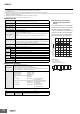
■ Characteristics
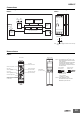
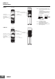
● Installation Pitch and Output
Switching Capacity (Reference
Values)
The relation between the installation pitch
and the load current is shown in the follow-
ing graph. (Except for the H3DK-GE)
If Timer is used under load conditions that
exceed the specified values, the tempera-
ture inside the Timer will increase, reduc-
ing the life expectancy of internal parts.
0 1 2 3 4 5 6
80
70
60
50
40
30
20
10
d = 5 mm
d
= 0 mm
d = 10 mm
d = 50 mm
Ambient temperature (°C)
Maximum ambient operating
temperature in specifications
Load current (A)
DIN Track Timer installation pitch: d
Tested Timer: H3DK-F
Applied voltage: 240 VAC
Installation pitch: 0, 5, 10, and 50 mm
Test
timer
1
Test
timer
2
Test
timer
3
Te st
timer
4
Te st
timer
5
Testing Method
■ Applicable standards
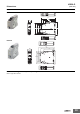
■ I/O
Accuracy of operating
time
±1% of FS max. (±1% ±10 ms max. at 1.2-s range)
Setting error ±10% of FS ±0.05 s max.
Influence of voltage ±0.5% of FS max. (±0.5% ±10 ms max. at 1.2-s range)
Influence of tempera-
ture
±2% of FS max. (±2% ±10 ms max. at 1.2-s range)
Insulation resistance 100 MΩ min. at 500 VDC
Dielectric strength
Between current-carrying metal parts and exposed non-current-carrying metal
parts: 2,000 VAC 50/60 Hz for 1 min.
Between control output terminals and operating circuit: 2,000 VAC 50/60 Hz for
1 min.
Between contacts not located next to each other: 1,000 VAC 50/60 Hz for
1min.
Impulse withstand volt-
age
24 to 240 VAC/VDC: 3 kV between power terminals, 4.5 kV between current-
carrying metal parts and exposed non-current-carrying metal parts
12 VDC: 1 kV between power terminals, 1.5 kV between current-carrying metal
parts and exposed non-current-carrying metal parts
Noise immunity
Square-wave noise generated by noise simulator (pulse width: 100 ns/1 µs,
1-ns rise): ±1.5 kV
Static immunity Malfunction: 4 kV, Destruction: 8 kV
Vibration
resistance
Destruction 0.75-mm single amplitude at 10 to 55 Hz for 2 h each in 3 directions
Malfunction 0.5-mm single amplitude at 10 to 55 Hz for 10 min each in 3 directions
Shock re-
sistance
Destruction 1,000 m/s
2
3 times each in 6 directions
Malfunction 100 m/s
2
3 times each in 6 directions
Life ex-
pectancy
Mechanical 10 million operations min. (under no load at 1,800 operations/h)
Electrical 100,000 operations min. (5 A at 250 VAC, resistive load at 360 operations/h)
Degree of protection IP30 (Terminal block: IP20)
Weight Approx. 110 g
Safety standards
cURus: UL 508/CSA C22.2 No. 14
EN 50274: Finger protection, back-of-hand proof
EN 61812-1: Pollution degree 2, Overvoltage category III
CCC: Pollution degree 2, Overvoltage category II, section DB14048.5-2008 part 5-1
LR: Test Specification No. 1-2002 Category ENV 1.2
EMC
(EMI) EN61812-1
Radiated Emissions: EN 55011 class B
Emission AC Mains: EN 55011 class B
Harmonic Current: EN 61000-3-2
Voltage Fluctuations and Flicker: EN61000-3-3
(EMS) EN61812-1
ESD Immunity: EN 61000-4-2: 6 kV contact discharge,
8 kV air discharge
Radiated Radio-Frequency Electromagnetic Field Immunity (AM Radio Waves):
EN 61000-4-3: 10 V/m (80 MHz to 1 GHz)
Burst Immunity: EN 61000-4-4: 2 kV power line,
1 kV I/O signal line
Surge Immunity: EN 61000-4-5: 2 kV common mode,
1 kV differential mode
Input None
Output Control output
Output is turned ON/OFF according to the time set on the ON
time setting dial and OFF time setting dial.