
Datasheet


H3CR-A
14
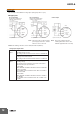
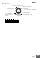
Gate Signal Input (This timing chart indicates the gate input in operating mode A (ON-delay operation).)
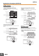
Operating
mode
Timing chart
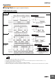
D:
Signal OFF-
delay
E:
Interval
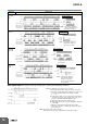
G:
Signal ON/
OFF-delay
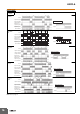
J:
One-shot
output
t
Basic operation
Power
Output
Output relay (NC)
Power indicator
Power
Start
Reset
Output relay (NO)
(Output indicator)
Start
(See note)
Note: Start input is valid and
retriggerable while the
Timer is in operation.
t
Power
Start
Reset
Output relay (NC)
Power indicator
Power
Output
Output relay (NO)
(Output indicator)
Basic operation
Start
(See note)
Note: Start input is valid and
retriggerable while the
Timer is in operation.
tttt
Basic operation
Power
Output
Power
Start
Reset
Output relay (NC)
Power indicator
Output relay (NO)
(Output indicator)
Start
(See note)
Note: Start input is valid and
retriggerable while the Timer
is in operation.
t
Basic operation
Output
Power
Power
Start
Reset
Output relay (NC)
Power indicator
Output relay (NO)
(Output indicator)
1±0.6 s
(Fixed)
1±0.6 s
(Fixed)
Start
(See note)
1±0.6 s
(Fixed)
Note: Start input is valid and
retriggerable while the
Timer is in operation.
(Previous start input will
be cancelled.)
t
1
t
2
Power
Start
Gate
Reset
ON
OFF
ON
OFF
ON
OFF
ON
OFF
ON
OFF
Output
relay
Note: 1. Allow a timer reset time of 0.1 s or longer.
2. The minimum input pulse width (for start, reset) is 0.05 s.
3. The letter "t" in the timing charts indicates the set time, and
"t-a" means that the period is less than the set time.
(t - a < 1)
4.
In J Mode, there will be only one output even if the start input is
longer than the set time. Power supply start in mode J is also
possible for H3CR-A8/-A8E/-A8S/-A8-301 models.
5. H3CR-AP model incorporates start input only.
6. Model H3CR-AS only has operation equivalent to time-limit
contact: NO.
7. When the setting dial is turned all the way past 0 for
intantaneous output, "t" (set time) in the above time chart is
0-sec operation.
Note: The set time is the sum of t1 and t2.
Start and reset are also both enabled when the gate signal is ON.