
Datasheet
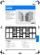

G-126 Safety Sensors / Components
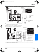
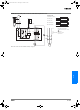
G9SB-200-D (24 VAC/VDC) or G9SB-301-D (24 VAC/VDC) with 2-channel Safety Area Sensor/Manual-reset
Note: This circuit conforms to EN954-1 Safety Category 4.
KM1
KM2
S1
KM1
KM2
E1
KM1
KM2
M
K1
K2
K1
K1
K2
K2 K1
a
a
+
-
K2
TH
SA
A1 A2
T11 T12 T31 T32
13
41
33
14 24
34 42
T21
T22
23
**
**
Emitter Receiver
Open
Open
Open
Open
Feedback loop
Control
circuit
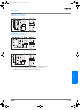
Timing Chart
F3SN-A: Incident
Interrupted
Reset switch S1
K1 and K2 (NC)
K1 and K2 (NO)
KM1 and KM2 (NC)
KM1 and KM2 (NO)
Note: Output turns ON with the rising edge of re-
set switch S1, but will not operate if there is
a short breakdown in S1.
F3SN-A: Safety Area Sensor
S1: Reset switch
KM1 and KM2: Magnetic Contactor
M: 3-phase motor
E1: 24-VDC power supply
Note: Only the G9SB-301-D
model has terminals
33-34 and 41-42.
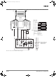
See note.
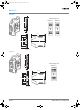
Shield
0V (Blue)
OSSD2 (White)
OSSD1 (Green)
Auxiliary (Yellow)
EDM input (Red)
+24 V (Brown)
F3SN-A
F3SH-A
+24 V (Brown)
Interlock selection
input (White)
Reset input (Yellow)
Test input (Green)
(Red)
0V (Blue)
Shield
RS-485(A) (Gray)
RS-485(B) (Pink)
F502-EN2-04.book Seite 126 Dienstag, 26. Juli 2005 5:48 17