
Datasheet


4
G9SB
G9SB
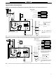
G9SB-200-D (24 VAC/VDC) or G9SB-301-D (24 VAC/VDC) with 2-channel Safety Area Sensor/Manual-reset
G9SB-3010 (24 VDC) with 2-channel Limit Switch Input/Auto-reset
KM1
KM2
S1
KM1
KM2
㧱㧝
㧱2
KM1
KM2
M
K1
K2
K1
K1
K2
K2 K1
a
a
+
-
K2
TH
SA
A1 A2
T11 T12 T31 T32
13
㧔41㧕
㧔33㧕
14
24
㧔34㧕㧔42㧕
T21
T22
23
㧖㧖
㧖㧖
Emitter Receiver
F3S-A
Shield
Red
Red/black
Shield
Feedback loop
Purple
Pink
Gray/black
Gray
Blue
Brown
Gray/black
White
Black
Gray
Blue
Brown
Control
circuit
Timing Chart
F3S-A: Safety Area Sensor
S1: Reset switch
KM1 and KM2: Magnetic Contactor (LC1D)
M: 3-phase motor
E1 and E2: 24-VDC power supply (S82K)
Note Output turns ON with the rising edge of re-
set switch S1, but will not operate if there
is a short breakdown in S1.
Note: 1. Connect E1 to
model other
than the F3S-A.
2. Only the G9SB-
301-D model
has terminals
33-34 and 41-
42.
Open
Open
Open
Open
F3S-A: Incident
Interrupted
K1 and K2 (NC)
K1 and K2 (NO)
KM1 and KM2 (NC)
KM1 and KM2 (NO)
Reset switch S1
KM1
KM2
M
KM1
KM2
11
12
23
24
S2
S1
KM1
KM2
K1
K2
K1
K1
K2
K2 K1
a
a
+
-
K2
TH
SA
A1 A2
T31 T32
13 23 33 41
14 24 34 42
Open
Control
circuit
Feedback loop
Timing Chart
Limit switches S1 and S2
K1 and K2 (NC)
K1 and K2 (NO)
KM1 and KM2 (NC)
KM1 and KM2 (NO)
S1: Safety limit switch with positive
opening mechanism (D4D or D4B)
S2: Limit switch
KM1 and KM2: Magnetic Contactor (LC1D)
M: 3-phase motor