
Datasheet
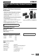


G7SA
9
Options (order separately)
Sockets
Accessories for Push-In Plus Sockets
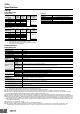
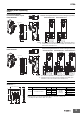
Short Bars (for P7SA-@F-ND-PU)
XW5S-P2.5-@@
A1 A2
(1)(0)
12 44 2434
11 43 2333
A1 A2
(1)(0)
12 44 2234
11 43 2133
(4)
3.4
35.4
61
35.4
4.5
22.5
100
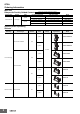
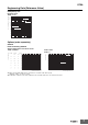
LED indicator
G7SA-3A1B Mounted
Terminals Arrangement/Internal Connections Diagram (Top View)
G7SA-2A2B Mounted
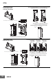
Front-mounting Sockets
Push-In Plus terminals 4 poles
P7SA-10F-ND-PU
Note: 1. The numbers in parentheses are traditionally used terminal numbers.
2. Terminals 23-24, 33-34, and 43-44 are normally open. Terminals 11-12
and 21-22 are normally closed.
A1 A2 (1)(0)
24
12
11
54 6434
23 53
44
43 6333
A1 A2 (1)(0)
22
12
11
54 6434
21 53
44
43 6333
A1 A2 (1)(0)
22
12
11
54 6432
21 53
44
43 6331
3.4
35.4
61
35.4
4.5
27.7
100
(4)
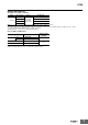
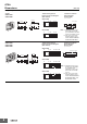
G7SA-5A1B Mounted
Terminals Arrangement/Internal Connections Diagram (Top View)
G7SA-4A2B Mounted G7SA-3A3B Mounted
LED indicator
Push-In Plus terminals 6 poles
P7SA-14F-ND-PU
Note: 1. The numbers in parentheses are traditionally used terminal numbers.
2. Terminals 23-24, 33-34, 43-44, 53-54, and 63-64 are normally open.
Terminals 11-12, 21-22, and 31-32 are normally closed.
5.2
P
23
3
1.6
5.2 × (No. of poles −1) +3.7
Note: Use for crossover wiring of adjacent contact terminals (bottom) within one Socket.
* Replace the box (@) in the model number with the code for the covering color.
Color Options: RD = red, BL = blue, YL = yellow
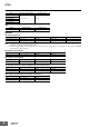
Pitch Compatible models No. of poles P (mm) Colors Model *
5.2 mm For P7SA-@F-ND-PU
2 5.2
Red (RD)
Blue (BL)
Yellow (YL)
XW5S-P2.5-2@
3 10.4 XW5S-P2.5-3@
4 15.6 XW5S-P2.5-4@
5 20.8 XW5S-P2.5-5@