
Datasheet


G7SA
8
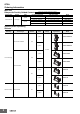
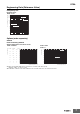
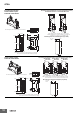
Dimensions (Unit: mm)
Safety Relay Unit
G7SA-2A2B
G7SA-4A2B
G7SA-3A3B
Ten, 1.4 dia.
(±0.1 tolerance)
(±0.1 tolerance)
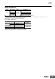
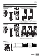
4 poles
G7SA-3A1B
G7SA-2A2B
6 poles
G7SA-5A1B
G7SA-4A2B
G7SA-3A3B
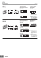
Terminal Arrangement/
Internal Connection Diagram
(Bottom View)
G7SA-3A1B
Printed Circuit Board
Design Diagram
(Bottom View)
Terminal Arrangement/
Internal Connection Diagram
(Bottom View)
G7SA-5A1B
Printed Circuit Board
Design Diagram
(Bottom View)
40 max.
0.5
13 max.
0.5
1
3.5
24 max.
11.43
5.08 5.08
13.97
10.16
(1.83)
11.43
5.08 5.08 5.08 5.08
13.97
10.16
(1.83)
13 max.
1
24 max.
3.5
0.5
0.5
50 max.
Fourteen, 1.4 dia.
34
43
33
442221
1211
1
0
−
+
−
+
34
43
33
442423
1211
1
0
−
+
54
6463
5332
43
31
442221
1211
1
0
−
+
54
6463
5334
43
33
442221
1211
1
0
−
+
54
6463
5334
43
33
442423
1211
1
0
Note: 1. Terminals 23-24, 33-34,
and 43-44 are normally
open. Terminals 11-12 and
21-22 are normally closed.
2. The colors of the cards
inside the Relays are as
follows: G7SA-3A1B: Blue
and G7SA-2A2B: White.
Note: 1. Terminals 23-24, 33-34,
43-44, 53-54, and 63-64
are normally open.
Terminals 11-12, 21-22,
and 31-32 are normally
closed.
2. The colors of the cards
inside the Relays are as
follows: G7SA-5A1B: Blue,
G7SA-4A2B: White, and
G7SA-3A3B: Yellow.