
Datasheet


G7SA
4
Specifications
Ratings
Safety Relay Unit
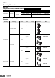
Coil (4 poles)
Coil (6 poles)
Note: 1. The rated current and coil resistance are measured at a coil
temperature of 23°C with tolerances of ±15%.
2. The maximum voltage is based on an ambient operating
temperature of 23°C maximum.
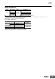
Contacts
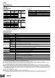
Characteristics
Safety Relay Unit
Note: 1. The above values are initial values.
2. Performance characteristics are based on coil temperature of 23°C.
*1. The contact resistance was measured with 1 A at 5 VDC using the voltage-drop method.
*2. These times were measured at the rated voltage and an ambient temperature of 23°C. Contact bounce time is not included.
*3. The response time is the time it takes for the normally open contacts to open after the coil voltage is turned OFF. Contact bounce time is
included. Measurement conditions: Rated voltage operation, Ambient temperature: 23°C
*4. The insulation resistance was measured with a 500-VDC megohmmeter at the same locations as the dielectric strength was measured.
*5. Pole 3 refers to terminals 31-32 or 33-34, pole 4 refers to terminals 43-44, pole 5 refers to terminals 53-54, and pole 6 refers to terminals 63-64.
*6.
When using a P7SA Socket, the dielectric strength between coil contacts/different poles is 2,500 VAC, 50/60 Hz for 1 min. When using Push-In Plus
terminal sockets (P7SA-
@
F-ND-PU), the dielectric strength between coil contacts as well as between different poles is 4,000 VAC, 50/60 Hz for 1 min.
*7. The durability is for an ambient temperature of 15 to 35°C and an ambient humidity of 25% to 75%. For the durability performance to the load,
refer to the Durability Curve.
*8. AC15: cosφ = 0.3, DC13: L/R = 48-ms.
*9. The failure rate is based on an operating frequency of 300 operations/min.
*10. 12 to 48 VDC: When operating between 70 and 85°C, reduce the rated carry current of 6 A by 0.1 A for each degree above 70°C.
110 VDC: When operating between 40 and 60°C, reduce the rated carry current of 6 A by 0.27 A for each degree above 40°C.
Rated voltage
Item Rated
current
(mA)
Coil
resistance
(Ω)
Max.
voltage
(V)
Power
consumption
(mW)
12 VDC 30 400
110%
Approx. 360
18 VDC 20 900
21 VDC 17.1 1,225
24 VDC 15 1,600
48 VDC 7.5 6,400
110 VDC 3.8 28,810 Approx. 420
Rated voltage
Item Rated
current
(mA)
Coil
resistance
(Ω)
Max.
voltage
(V)
Power
consumption
(mW)
12 VDC 41.7 288
110%
Approx. 500
18 VDC 27.8 648
21 VDC 23.8 882
24 VDC 20.8 1,152
48 VDC 10.4 4,606
110 VDC 5.3 20,862 Approx. 580
Item Load Resistive load
Rated load 6 A at 250 VAC, 6 A at 30 VDC
Rated carry current 6 A
Max. switching voltage 250 VAC, 125 VDC
Max. switching current 6 A
Contact materials Au plating + Ag alloy
Contact resistance *1 100 mΩ max.
Operating time *2 20 ms max.
Response time *3 10 ms max.
Release time *2 20 ms max.
Must operate voltage 75% max.
Must release voltage 10% min.
Maximum operating
frequency
Mechanical 36,000 operations/h
Rated load 1,800 operations/h
Insulation resistance *4 1,000 MΩ min.
Dielectric Strength
*5 *6
Between coil and
contacts
4,000 VAC, 50/60 Hz for 1 min.
Between
contacts of
different polarity
4,000 VAC, 50/60 Hz for 1 min. (except for followings)
4 poles (for poles 3-4 in 4-pole Relays),
6 poles (for poles 3-5, 4-6, and 5-6 in 6-pole Relays): 2,500 VAC, 50/60 Hz for 1 min.
Between contacts
of the same polarity
1,500 VAC, 50/60 Hz for 1 min.
Vibration resistance 10 to 55 to 10 Hz, 0.75-mm single amplitude (1.5-mm double amplitude)
Shock resistance
Destruction 1,000 m/s
2
Malfunction 100 m/s
2
Durability *7
Mechanical 10,000,000 operations min. (at approx. 36,000 operations/h)
Electrical 100,000 operations min. (at the rated load)
Inductive load switching capability
*8
(IEC60947-5-1)
AC15 240 VAC, 2 A
DC13 24 VDC, 1 A/48 VDC, 0.5 A/110 VDC, 0.2 A
Failure rate (P level)
(reference value *9)
5 VDC, 1 mA
Ambient operating temperature
*10
12 to 48 VDC: -40 to 85°C (with no icing or condensation)
110 VDC: -40 to 60°C (with no icing or condensation)
Ambient operating humidity 5% to 85%
Weight
4 poles: Approx. 22 g
6 poles: Approx. 25 g