
Datasheet

G7SA
14
<Using with back-connecting sockets, PCB terminal sockets
(P7SA-10P, P7SA-14P)>
Refer to Common Precautions for All Relays with Forcibly Guided
Contacts at the following URL: http://www.ia.omron.com/.
5-1-3. Soldering of Terminals
5-2. PCB Relays
5-3. Common Items
Push-In Plus Terminal Sockets (P7SA-
@
F-ND-PU)
1. Connecting Wires to the Push-In Plus Terminal Block
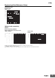
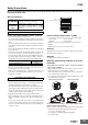
Part Names of the Terminal Block
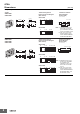
Connecting Wires with Ferrules and Solid Wires
Insert the solid wire or ferrule straight into the terminal block until the
end strikes the terminal block.
• If a wire is difficult to connect because it is too thin, use a flat-blade
screwdriver in the same way as when connecting stranded wire.
Connecting Stranded Wires
Use the following procedure to connect the wires to the terminal block.
1. Hold a flat-blade screwdriver at an angle and insert it into the
release hole.
The angle should be between 10° and 15°. If the flat-blade
screwdriver is inserted correctly, you will feel the spring in the
release hole.
2. With the flat-blade screwdriver still inserted into the release hole,
insert the wire into the terminal hole until the end strikes the
terminal block.
3.
Remove the flat-blade screwdriver from the release hole.
Checking Connections
• After the insertion, pull gently on the wire to make sure that it will
not come off and the wire is securely fastened to the terminal block.
• If you use a ferrule with a conductor length of 10 mm, part of the
conductor may be visible after the ferrule is inserted into the
terminal block, but the product insulation distance will still be
satisfied.
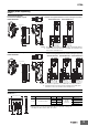
2. Removing Wires from the Push-In Plus Terminal Block
Use the following procedure to remove wires from the terminal block.
The same method is used to remove stranded wires, solid wires, and
ferrules.
1. Hold a flat-blade screwdriver at an angle and insert it into the
release hole.
2. With the flat-blade screwdriver still inserted into the release hole,
remove the wire from the terminal insertion hole.
3.
Remove the flat-blade screwdriver from the release hole.
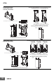
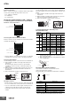
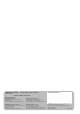
3. Recommended Ferrules and Crimp Tools
Recommended ferrules
Note: 1. Make sure that the outer diameter of the wire coating is
smaller than the inner diameter of the insulation sleeve of
the recommended ferrule.
2. Make sure that the ferrule processing dimensions conform
to the following figures.
Recommended Flat-blade Screwdriver
Use a flat-blade screwdriver to connect and remove wires.
Use the following flat-blade screwdriver.
The following table shows manufacturers and models as of 2015/Dec.
* OMRON's exclusive purchase model XW4Z-00B is available to
order as SZF 0-0,4×2,5 (manufactured by Phoenix Contact).
Release hole
Terminal (insertion) hole
Release hole
Terminal (insertion) hole
Ferrules or solid wires
1
3
2
2
Flat-blade
screwdriver
10 to15°
1
3
Stranded wires
Applicable
wire
Ferrule
Conductor
Length
(mm)
Stripping
length
(mm)
(Ferrules
used)
Recommended ferrules
(mm
2
) (AWG)
Phoenix Contact
product
Weidmuller
product
Wago
product
0.5 20
8 10 AI 0,5-8 H0.5/14 216-201
10 12 AI 0,5-10 H0.5/16 216-241
0.75 18
8 10 AI 0,75-8 H0.75/14 216-202
10 12 AI 0,75-10 H0.75/16 216-242
1/1.25 18/17
8 10 AI 1-8 H1.0/14 216-203
10 12 AI 1-10 H1.0/16 216-243
1.25/1.5
17/16
8 10 AI 1,5-8 H1.5/14 216-204
10 12 AI 1,5-10 H1.5/16 216-244
Recommended crimp tool
CRIMPFOX6
CRIMPFOX6T-F
CRIMPFOX10S
PZ6 roto
Variocrimp4
Model Manufacturer
SZS 0,4×2,5
SZF 0-0,4×2,5 *
Phoenix Contact
ESD 0,40×2,5 Wera
0.4×2.5×75 302 Wiha
AEF.2,5×75 Facom
210-719 Wago
SDI 0.4×2.5×75 Weidmuller
1
3
2
2
10 to 15°
Wire
Flat-blade
screwdriver
1
3
8 to 10 mm
1.9 mm max.
2.6 mm max.
Side
0.4 mm
2.5 mm dia.
2.5 mm
Front