
Datasheet


G7SA
13
Safety Precautions
Be sure to read the Common Precautions for All Relays with Forcibly Guided Contacts at the following URL:
http://www.ia.omron.com/.
Warning Indications
Push-In Plus Terminal Sockets (P7SA-
@
F-ND-PU)
• Do not wire anything to the release holes.
• Do not tilt or twist a flat-blade screwdriver while it is inserted into a
release hole on the terminal block. The terminal block may be dam-
aged.
• Insert a screwdriver into the release holes at an angle. The terminal
block may be damaged if the flat-blade screwdriver is inserted
straight in.
• Do not allow the flat-blade screwdriver to fall when you are holding
it in a release hole.
• Do not bend a wire past its natural bending radius or pull on it with
excessive force. Doing so may cause the wire disconnection.
• Do not insert more than one wire into each terminal insertion hole.
• To prevent wiring materials from smoking or igniting, confirm wire
ratings and use the wiring materials given in the following table.
• Insert a flat-blade screwdriver all the way to the bottom of the
release hole. If the flat-blade screwdriver is not inserted correctly,
the wire may not be connected correctly.
• When crossover wiring with wires or short bars, make sure not to
insert them in the wrong position. It may cause a short circuit, a
malfunction, or a failure.
Wiring
• The coil terminals have polarity (+, −). Inverting the polarity when
wiring the terminals will cause the unit not to operate.
• The release time and the response time of the G7SA will be longer
when using the P7SA-@F-ND(-PU) because it has a built-in diode to
absorb coil surge. Because of that, confirm operation under actual
conditions before using the P7SA-@F-ND(-PU).
<Using with P7SA-@F-ND-PU Push-In Plus terminal sockets>
• If there is lubrication, such as oil, on the tip of the flat-blade screw-
driver, the flat-blade screwdriver may fall and possibly injure a
worker.
• Do not insert short bar in the hole for wire or screw driver, it may
cause the result of failure of pull out. If insert short bar in the hole
for wire or screw driver and try to pull out, it may cause damage for
short bar or socket.
Screw Terminal Sockets (P7SA-@F(-ND))
• Use one of the following wires to connect to the P7SA-@F(-ND).
Stranded wire: 0.75 to 1.5 mm
2
Solid wire: 1.0 to 1.5 mm
2
• Tighten the screws of the P7SA-@F(-ND) to a torque of 0.78 to
0.98 N·m.
Tighten firmly so as not to have any loose wires.
Cleaning
The G7SA is not of enclosed construction. Therefore, do not wash the
G7SA with water or detergent.
Mounting
The G7SA can be installed in any direction.
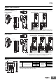
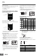
Mounting and Removing the Relays to and from
the Socket
<Using with front-connecting sockets, Push-In Plus terminal
sockets (P7SA-@F-ND-PU)>
• After mounting the relay, make sure to lock the lock hook. If not, the
relay may become loose upon vibration or impact.
• When removing the relay, (1) unlock the lock hook on the release
side, (2) then press the release lever.
• You can release the locked block easily by inserting a tip of a flat
screwdriver into the square hole.
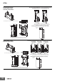
<Using with front-connecting sockets, screw terminal sockets
(P7SA-10F(-ND), P7SA-14F (-ND))>
Refer to Common Precautions for All Relays with Forcibly Guided
Contacts at the following URL: http://www.ia.omron.com/.
5-1-1. Front-connecting Sockets
5-1-2. Direction for Inserting and Removing Relays
5-3. Common Items
Precautions
for Safe Use
Supplementary comments on what to do or
avoid doing to use the product safely.
Precautions
for Correct
Use
Supplementary comments on what to do or
avoid doing to prevent failure to operate,
malfunction, or undesirable effects on product
performance.
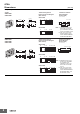
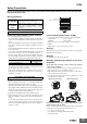
Precautions for Safe Use
Recommended wire
Stripping length
(Ferrules not used)
0.25 to 1.5mm
2
/AWG24 to 16 8 mm
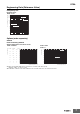
Precautions for Correct Use
Release hole
Terminal (insertion) hole
Short bar insertion holes
With the relay mounted
Removing the relay
Lock hook
Release lever
(2)
(1)