
Datasheet


G7SA
10
44 33 34
43
24
23
12
11 1 0 11 1 0
44
33 34
43
22
21
12
22.5 max.
2R
Ten,
M3×8
9 max.
5
9 max.
80
±0.2
60.5 max.
72 max.
LED
indicator
4 dia.
14.5
±0.2
Two, 4 dia.
or M3.5
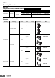
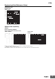
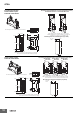
G7SA-3A1B Mounted
Terminal Arrangement/Internal Connection Diagram (Top View)
Mounting Hole Placement Diagram (Top View)
G7SA-2A2B Mounted
**
* This display circuit is available only for "-ND" models.
Note: Terminals 23-24, 33-34, and 43-44 are normally open.
Terminals 11-12 and 21-22 are normally closed.
2: Only the -ND Sockets have LED indicators (orange)
Note 1: The front view shows with the finger cover removed.
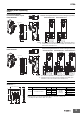
Front-mounting Sockets
Screw terminals 4 poles
P7SA-10F, P7SA-10F-ND
The above figure shows with the finger cover mounted.
64
63
44
43
24
23 1 0 11
12
33
34
53
54
64
63
44
43
22
21 1 0 11
12
33
34
53
54
64
63
44
43
22
21 1 0 11
12
31
32
53
54
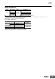
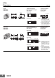
G7SA-5A1B
Mounted
Terminal Arrangement/Internal Connection Diagram (Top View)
Mounting Hole Placement Diagram (Top View)
G7SA-3A3B
Mounted
G7SA-4A2B
Mounted
30 max.
9 max.
9 max.
5
80
±0.2
60.5 max.
72 max.
4 dia.
22
±0.2
Two, 4 dia.
or M3.5
2R
Fourteen,
M3 × 8
LED
indicator
***
* This display circuit is available only for "-ND" models.
Note: Terminals 23-24, 33-34, 43-44, 53-54, and 63-64 are normally
open. Terminals 11-12, 21-22, and 31-32 are normally closed.
2: Only the -ND Sockets have LED indicators (orange).
Note 1: The front view shows with the finger cover removed.
Screw terminals 6 poles
P7SA-14F, P7SA-14F-ND
The above figure shows with the finger cover mounted.