
Datasheet


14 Solid State Relays G3NA
EMC Directive Compliance (For -UTU type)
EMC directives can be complied with under the following conditions.
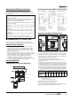
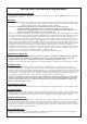
1. AC-switching models
• A capacitor must be connected to the input power supply.
• A capacitor, varistor and toroidal core must be connected to the
load power supply.
• The input cable must be less than 3 m.
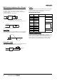
2. DC-switching models
• The input cable must be less than 3 m.
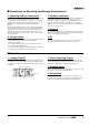
Loss Time
The loss time will increase when the G3NA is used at a low applied
voltage or current. Be sure that this does not cause any problems.
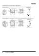
Using DC Loads
For a DC or L load, a diode should be connected in parallel the load
to absorb the counter electromotive force of the load.
Fuses
Connect a quick-break fuse in series with the load as a short-circuit
protection measure. Use one of the fuses in the following table or
one with equivalent or better characteristics.
Recommended Fuses
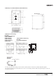
Reverse Connection
The output terminal side of the G3NA-D210B is connected to a built-
in diode to protect the SSR from damage that may result from
reverse connection. The SSR, however, cannot withstand one minute
or more if the wires are connected in reverse. Therefore, pay the
utmost attention not to make polarity mistakes on the load side.
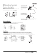
G3NA
Output
Input
Recommended Capacitor : 0.05µF, 500 VAC (Load)
0.1µF, 250 VAC (Input)
Recommended Varistor : 470 V, 1750 A
Recommended Troidal core : NEC/TOKIN:ESD-R-25B or equivalent
Troidal core
Load
3 m max.
Output Input
G3NA-UTU
Load
Less than 3 m
Loss time
SSR
Input
Load
Load power
supply
G3NA rated
load current
Fuse model Manufacturer
Applicable SSR
5 A 60LFF5 HINODE ELECTRIC
CO.,LTD.
G3NA-205B-UTU
8 A 60LFF8 G3NA-210B-UTU
10 A 60LFF10
15 A 60LFF15 G3NA-220B-UTU
20 A 60LFF20
50SHA20
25 A 60PFF25
50SHA25
G3NA-240B-UTU
30 A 60PFF30
50SHA30
G3NA-250B-
UTU
40 A 50SHA40
45 A 50SHA45
50 A 50SHA50
75 A 50SHA75 G3NA-275B-UTU(-2)
80 A 50SHA80 G3NA-290B-UTU(-2)
100 A 50SHB100