
Datasheet


5
EE-SX47/67
PNP Output
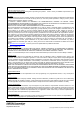
*1. Do not connect the L terminal to 0 V when using dark-ON operation.
*2. If you do not use the L terminal wire ((2) pink) when you use a Connector with Cable for an EE-1006 or EE-1010-series Photomicrosensor, noise may affect the
Photomicrosensor. To prevent the effects of noise, cut the unused L terminal wire at the base of the connector and wrap it with insulating tape to prevent it from
coming in contact with other terminals.
Safety Precautions
Refer to Warranty and Limitations of Liability.
This product is not designed or rated for ensuring
safety of persons either directly or indirectly.
Do not use it for such purposes.
● Operating Environment
These Photomicrosensors have an IP50 (conforms to IEC) enclosure
and do not have a water-proof or dust-proof structure. Therefore, do
not use them in applications in which the sensor will be subjected to
splashes from water, oil, or any other liquid. Liquid entering the
Sensor may result in malfunction.
Make sure that this product is used within the rated ambient
environment conditions.
● Installation
• When direct soldering to the terminals, use the following guidelines.
Soldering Conditions
•
The terminal base uses a polycarbonate resin, which could be deformed by
excessive soldering heat, resulting in damage to the product's functionality.
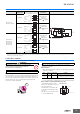
● Lot Number and Model Number Legend
In the following diagrams, 343U
indicates the lot number and factory
where the product was
manufactured. Do not include this
code with the model number when
ordering.
The QR code on connector models
is used by OMRON only.
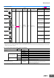
Model
Output
configuration
Timing charts
Terminal
connections
Output circuit
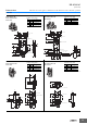
EE-SX67@P
EE-SX67@P-WR
Light-ON
Short-circuited
between
terminal and
positive terminal
Dark-ON
Open between
terminal and
positive terminal
*1 *2
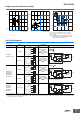
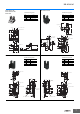
EE-SX670R
EE-SX671R
EE-SX672R
EE-SX673R
EE-SX674R
Light-ON
Short-circuited
between
terminal and
positive terminal
Dark-ON
Open between
terminal and
positive terminal
*1 *2
Incident
Interrupted
ON
OFF
ON
OFF
Operates
Releases
Light indicator
(red)
Output
transistor
Load
(relay)
L
5 to
24 VDC
Load
Main
circuit
L
OUT
IC
Light indicator
(red)
*
*The terminal arrangement depends on the model.
Check the dimensional diagrams.
Incident
Interrupted
ON
OFF
ON
OFF
Operates
Releases
Light indicator
(red)
Output
transistor
Load
(relay)
L
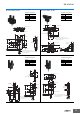
Incident
Interrupted
ON
OFF
ON
OFF
Operates
Releases
Light indicator
(red)
Output
transistor
Load
(e.g., relay)
L
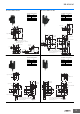
Incident
Interrupted
ON
OFF
ON
OFF
Operates
Releases
Light indicator
(red)
Output
transistor
Load
(e.g., relay)
L
WARNING
Precautions for Safe Use
Precautions for Correct Use
Item
Temper-
ature
Permissible
time
Remarks
Soldering
iron
350°C
max.
3 s max.
The portion between the base of the
terminals and the position 1.5 mm from
the terminal base must not be soldered.
Lot number and factory code
Model number
EE-SX670
343U
EE-SX@70@