
Datasheet


E5CC-T
74
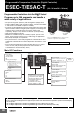
External Connections
E5CC-T
Note: 1. The application of the terminals depends on the model.
2. Do not wire the terminals that are shown with a gray background.
3. When complying with EMC standards, the cable that connects the sensor must be 30 m or less.
If the cable length exceeds 30 m, compliance with EMC standards will not be possible.
4. Connect M3 crimped terminals.
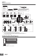
Isolation/Insulation Block Diagrams
Models with 3 Auxiliary Outputs
17
18 12
15
16
1
2
13
14
3
11
4
6
7
8
9
10
5
6
4
5
6
5
6
Pt
+
−
mA
−
+
5
4
(5) Sensor (Temperature/Analog) Input
V
−
5
V
6
+
4
TC
4
I
(no polarity)
11
12
(3) Input Power Supply
11
12
100 to 240 VAC 24 VAC/DC
(2) Auxiliary Outputs
Auxiliary outputs 1, 2, and 3
7
8
9
10
Auxiliary output 2
Auxiliary output 3
Auxiliary output 1
+
+
−
16
17
18
13
16
17
18
13
14
15
18
13
14
15
16
17
18
16
17
005
Event inputs 1 to 4
004
Communications (RS-485)
and event inputs 3 and 4
13
006
Event inputs 1 and 2, and
transfer output
(6) Options
001
Event inputs 1 and 2,
and CT1
V
I
003
Communications
(RS-485), CT1, and CT2
14
15
14
15
EV1
EV2
EV1
EV2
EV3
EV4
EV3
EV4
B(+)
A(−)
RS-485
B(+)
A(−)
RS-485
CT2
COM
CT1
+
−
3
1
2
3
1
2
−
Models with
1 Relay
Output
3
+
Q
1
+
2
−
3
(1) Control outputs 1, 2
Q
1
2
Models with 1
Voltage Output
(for Driving SSR)
+
RX QX CX QQ
CQR
OUT1 OUT1 OUT1 OUT1
OUT2
A
B
B
Voltage output
(for driving SSR)
12 VDC, 21 mA
Relay output
250 VAC: 2 A
(resistive load)
3
+
1
+
2
-
OUT1
C
OUT2
Q
CQ
E5CC
M
13
14
15
16
17
18
EV1
EV2
CT1
+
+
−
Transfer output
Control output 2
Auxiliary outputs
−
+
+
−
+
+
−
+
+
−
+
+
3
5
(1) (2) (3) (4) (5) (6)
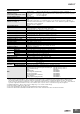
Terminal type
The E5CC-T is set for a K-type thermocouple (input
type = 5) by default. An input error (s.err) will occur
if the input type setting does not agree with the
temperature sensor. Check the input type.
Relay output
250 VAC, 3 A
(resistive load)
Voltage output
(for driving SSR)
12 VDC, 21 mA
Linear current output
0 to 20 mA DC
4 to 20 mA DC
Load: 500 Ω max.
Control output 1
Models with 1
Linear Current
Output
Models with 2
Voltage Outputs
(for Driving SSR)
Models with 2 Outputs:
Linear Current Output
and Voltage (for Driving SSR)
T
Models with 3 auxiliary outputs:
Sensor input and CT inputs
Communications and event inputs
Voltage output (for driving SSR),
linear current output, and transfer output
Relay output
Auxiliary outputs 1, 2, 3
: Reinforced insulation
: Functional isolation
Power
supply
Note: Auxiliary outputs 1 to 3 are not insulated.