
Datasheet


E5@C/E5@C-T
109
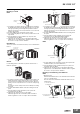
Attaching the End Cover
E5DC
1. Install the E5DC in a panel.
2. Peel off the release paper from the double-sided tape on the End
Cover.
3. Align the tabs on the End Cover with the depressions on the E5DC
and attach the End Cover.
4. Secure the End Cover so that the double-sided tape is firmly
attached.
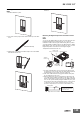
Removing the Digital Temperature Controller from the
case
E5GC
You can use the Y92F-55 Draw-out Jig to remove the interior body of
the Digital Temperature Controller from the case to perform
maintenance without removing the terminal wiring. This is possible
only for the E5GC. It is NOT possible for the E5CC, E5CC-U, E5EC,
E5AC, E5DC, or E5@C-T. Check the specifications of the case and
Digital Temperature Controller before removing the Digital
Temperature Controller from the case.
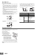
1. Insert the Y92F-55 Draw-out Jig securely into the Draw-out Jig
insertion holes (one hole each on the top and bottom) and press it
in firmly until the hooks engage on the top and bottom.
2. Pull out the Y92F-55 Draw-out Jig together with the front panel.
Do not apply unnecessary force.
3. When inserting the body of the Temperature Controller into the
case, make sure the PCBs are parallel to each other, make sure
that the sealing rubber is in place, and press the E5GC toward the
rear case into position. While pushing the E5GC into place, push
down on the hooks on the top and bottom surfaces of the rear case
so that the hooks are securely locked in place. Be sure that
electronic components do not come into contact with the case.
Double-sided tape
Draw-out Jig
insertion hole
Draw-out Jig
insertion hole
1
1
2
Y92F-55
Draw-out Jig
Panel
Mounting Adapter
3
Hook
Hook
Right Side View of the E5GC
Sealing rubber
PCBs
Keep the PCBs parallel to
each other and inset them
into the rear case.