
Datasheet


E5@C/E5@C-T
106
30.Noise may enter on the USB-Serial Conversion Cable, possibly
causing equipment malfunctions. Do not leave the USB-Serial
Conversion Cable connected constantly to the equipment.
31.For the E5DC, when you attach the Main Unit to the Terminal Unit,
make sure that the hooks on the Main Unit are securely inserted
into the Terminal Unit.
32.For the E5CC-U, when you attach the Main Unit to the socket,
make sure that the hooks on the socket are securely inserted into
the Main Unit.
33.Install the DIN Track vertically to the ground.
34.For the E5DC, always turn OFF the power supply before
connecting the Main Unit to or disconnecting the Main Unit from
the Terminal Unit, and never touch nor apply shock to the
terminals or electronic components. When connecting or
disconnecting the Main Unit, do not allow the electronic
components to touch the case.
35.Observe the following precautions when you remove the terminal
block or pulling out the interior of the product of the E5GC.
• Always follow the instructions provided in the E5@C Digital
Temperature Controllers User’s Manual (Cat. No. H174).
• Turn OFF the power supply before you start and never touch
nor apply shock to the terminals or electric components.
When you insert the interior body of the Digital Temperature
Controller, do not allow the electronic components to touch
the case.
• Check for any corrosion on the terminals.
• When you insert the interior body into the rear case, confirm
that the hooks on the top and bottom are securely engaged
with the case.
The E5CC, E5CC-U, E5EC, and E5AC comply with Lloyd's
standards. When applying the standards, the following installation
requirements must be met in the application.
Application Conditions
● Installation Location
The E5CC, E5CC-U, E5EC, and E5AC comply with installation
category ENV1 and ENV2 of Lloyd's standards. Therefore, they must
be installed in a location equipped with air conditioning. They cannot
be used on the bridge or decks, or in a location subject to strong
vibration.
● Service Life
1.
Use the product within the following temperature and humidity ranges:
Temperature: -10 to 55°C (with no icing or condensation)
Humidity: 25% to 85%
If the product is installed inside a control board, the ambient
temperature must be kept to under 55°C, including the temperature
around the product.
2.
The service life of electronic devices like Digital Temperature
Controllers is determined not only by the number of times the relay is
switched but also by the service life of internal electronic components.
Component service life is affected by the ambient temperature: the
higher the temperature, the shorter the service life and, the lower
the temperature, the longer the service life. Therefore, the service
life can be extended by lowering the temperature of the Digital
Temperature Controller.
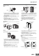
3. When two or more Digital Temperature Controllers are mounted
horizontally close to each other or vertically next to one another,
the internal temperature will increase due to heat radiated by the
Digital Temperature Controllers and the service life will decrease.
In such a case, use forced cooling by fans or other means of air
ventilation to cool down the Digital Temperature Controllers. When
providing forced cooling, however, be careful not to cool down the
terminals sections alone to avoid measurement errors.
● Measurement Accuracy
1.
When extending or connecting the thermocouple lead wire, be sure to
use compensating wires that match the thermocouple types.
2.
When extending or connecting the lead wire of the platinum resistance
thermometer, be sure to use wires that have low resistance and keep
the resistance of the three lead wires the same.
3. Mount the product so that it is horizontally level.
4. If the measurement accuracy is low, check to see if input shift has
been set correctly.
● Waterproofing (Not applicable to the E5CC-U/
E5DC.)
The degree of protection is as shown below. Sections without any
specification on their degree of protection or those with IP@0 are not
waterproof.
Front panel: IP66, Rear case: IP20, Terminal section: IP00
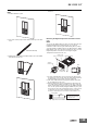
When waterproofing is required, insert the Waterproof Packing on the
backside of the front panel. Keep the Port Cover on the front-panel
Setup Tool port of the E5EC/E5AC/E5EC-T/E5AC-T securely closed.
The degree of protection when the Waterproof Packing is used is
IP66. To maintain an IP66 degree of protection, the Waterproof
Packing and the Port Cover for the front-panel Setup Tool port must
be periodically replaced because they may deteriorate, shrink, or
harden depending on the operating environment. The replacement
period will vary with the operating environment. Check the required
period in the actual application. Use 3 years or sooner as a guideline.
If the Waterproof Packing and Port Cover are not periodically
replaced, waterproof performance may not be maintained. If a
waterproof structure is not required, then the Waterproof Packing
does not need to be installed.
● Operating Precautions
1. When using self-tuning, turn ON power for the load (e.g., heater)
at the same time as or before supplying power to the Digital
Temperature Controller. If power is turned ON for the Digital
Temperature Controller before turning ON power for the load, self-
tuning will not be performed properly and optimum control will not
be achieved.
When starting operation after the Digital Temperature Controller
has warmed up, turn OFF the power and then turn it ON again at
the same time as turning ON power for the load. (Instead of turning
the Digital Temperature Controller OFF and ON again, switching
from STOP mode to RUN mode can also be used.)
2. Avoid using the Digital Temperature Controller in places near a
radio, television set, or wireless installing. These devices can
cause radio disturbances which adversely affect the performance
of the Controller.
● Others
1. Do not Connect or disconnect the Conversion Cable connector
repeatedly over a short period of time.
The computer may malfunction.
2. After connecting the Conversion Cable to the computer, check the
COM port number before starting communications. The computer
requires time to recognize the cable connection. This delay does
not indicate failure.
3. Do not connect the Conversion Cable through a USB hub. Doing
so may damage the Conversion Cable.
4. Do not use an extension cable to extend the Conversion Cable
length when connecting to the computer. Doing so may damage
the Conversion Cable.
Shipping Standards
Precautions for Correct Use