
User Manual


E5CD/E5CD-B
13
E5CD-B (Push-In Plus Terminal Blocks)
Note: 1. The application of the terminals depends on the model.
2. Do not wire the terminals that are shown with a gray
background.
3. When complying with EMC standards, the cable that
connects the sensor must be 30 m or less.
If the cable length exceeds 30 m, compliance with EMC
standards will not be possible.
4. Refer to E5
@
D-B (Push-In Plus terminal block types) on
page 48 for wire specifications and wiring methods.
5. Common terminals are indicated with
asterisks (*).
You can use the input power supply
and communications common
terminals for crossover wiring.
Controllers given below if you use
crossover wiring for the input power
supply.
100 to 240 VAC Controllers: 16 max.
24 VAC/VDC Controllers: 8 max.
6.
Due to UL Listing requirements, use the E54-CT1L or E54-CT3L
Current Transformer with the factory wiring (internal wiring).
Use a UL category XOBA or XOBA7 current transformer that is UL
Listed for field wiring (external wiring) and not the factory wiring
(internal wiring).
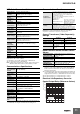
Isolation/Insulation Block Diagrams
E5CD E5CD-B
23
19
22
1
2
17
18
3
15
24 16
6
8
9
14
21513
20412
11
10
7
(2) Auxiliary Outputs
Auxiliary output 2
Auxiliary output 1
+
+
−
17
18
19
20
004
Communications (RS-485),
Event Inputs 3 and 4
006
Event inputs 1and 2,
and transfer output
001
Event Inputs 1
and 2, and CT1
21
22
23
24
V
I
002
Communications
(RS-485), CT1
Transfer
Output
EV2
EV1
(
−
)
(
−
)
(
−
)
(
−
)
(
−
)
(
−
)
EV2
EV1
EV4
EV3
CT1CT1
B(+)
A(
−
)
RS-485
B(+)
A(
−
)
RS-485
13
14
15
16
9
10
11
12
*
*
*
13
14
15
16
*
*
* * * *
*
*
*
8
6
7
8
Pt
A
B
B
+
−
m
A
−
+
7
6
V
−
V
+
TC
I
6
7
8
6
7
8
17
18
19
20
21
22
23
24
17
18
19
20
21
22
23
24
17
18
19
20
21
22
23
24
Use non-voltage inputs for the event
inputs.
The polarity for a non-contact input
is indicated by “(−).”
Relay output
250 VAC, 3 A (resistive load)
Voltage output
(for driving SSR)
12 VDC, 21 mA
Linear current output
0 to 20 mA DC
4 to 20 mA DC
Load: 500 Ω max
Relay outputs
250 VAC, 2 A (resistive load)
Control output 1
Auxiliary outputs 1, 2
The E5CD-B is set for a K-type thermocouple (input type = 5) by
default. An input error (s.err) will occur if the input type setting does
not agree with the temperature sensor. Check the input type.
E5CD-@@ 2 @ B M - @@@
↑
Terminal type
(1) (2) (3) (4) (5) (6)
Models with
1 Relay Output
(1) Control output 1
Models with 1
Voltage Output
(for Driving SSR)
OUT1
R
1
2
RX
1
2
OUT1
Q
QX
+
−
Models with 1
Linear Current Output
1
2
OUT1
C
CX
+
−
(5) Sensor (Temperature/Analog) Input
(3) Input Power Supply
100 to 240 VAC
24 VAC/DC
(no polarity)
(6) Options
Wiring Example:
To another E5CD-B
13
14
15
16
Sensor input and CT input
Communications and event inputs
Voltage output (for driving SSR),
linear current output, and transfer output
Relay output
Auxiliary output 1
: Reinforced insulation
: Functional isolation
Power
supply
Auxiliary output 2
Sensor input and CT input
Communications and event inputs
Voltage output (for driving SSR),
linear current output, and transfer output
Relay output
Auxiliary output 1, 2
: Reinforced insulation
: Functional isolation
Power
supply