
User Manual


189
Thermocouple Calibration (Thermocouple/Resistance Thermometer Input)
Section 6-3
Input types 6, 8, 9, 10, 13, 14,
16,17, 18, 19, 20, 21, and 22 only:
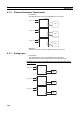
8. Press the M key. The display changes as shown on the left for input types
6, 8, 9, 10, 13, 14, 16, 17, 18, 19, 20, 21, and 22. Set the STV to
−6mV.
Allow the count value on the No. 2 display to fully stabilize, then press the
D key to temporarily register the calibration settings.
If this count value is outside of the specified range, the No. 2 display will
flash and the count value will not be temporarily registered.
9. When the M key is pressed, the status changes as shown to the left.
10. Change the wiring as follows:
Disconnect the STV to enable the thermocouple of the cold junction com-
pensator. When doing this, be sure to disconnect the wiring on the STV
side.
11. Allow the count value on the No. 2 display to fully stabilize, then press the
D key to temporarily register the calibration settings.
12. When the M key is pressed, the status changes as shown to the left.
The data to be temporarily registered is not displayed if it is not complete.
Press the U key. The No. 2 display changes to yes. Release the key and
wait two seconds or press the M key. This stores the temporarily regis-
tered calibration data to EEPROM. To cancel the saving of temporarily
registered calibration data to EEPROM, press the M key (while no is dis-
played in the No. 2 display) without pressing the U key.
13. The calibration mode is ended by turning the power OFF.
c--6
29be
bias
35b8
STV
DMM
OUTPUT INPUT
−
+
Open in non-connected state
Short-circuit
Compensating conductor of currently
selected thermocouple
Use K thermocouple compensating
conductor for E, R, S, and B thermocouples
and for an infrared temperature sensor.
Zero
controller
str
no