
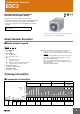
Datasheet


3
Specifications
■ Ratings
Note: 1. Do not use an inverter output as the power supply. (Refer to
Safety Precautions for All Temperature Controllers.)
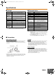
■ Characteristics
Note: 1. No reset function is incorporated by any E5C2 model with
ON/OFF control.
The reset function is used to correct offset for proportional
control. If there is an offset below the set value, turn the
reset adjustment clockwise.
2. A special Watertight Cover is used to achieve this degree of
protection (IP66, NEMA4). Refer to Y92A-
@@
N.
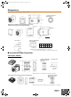
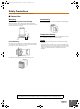
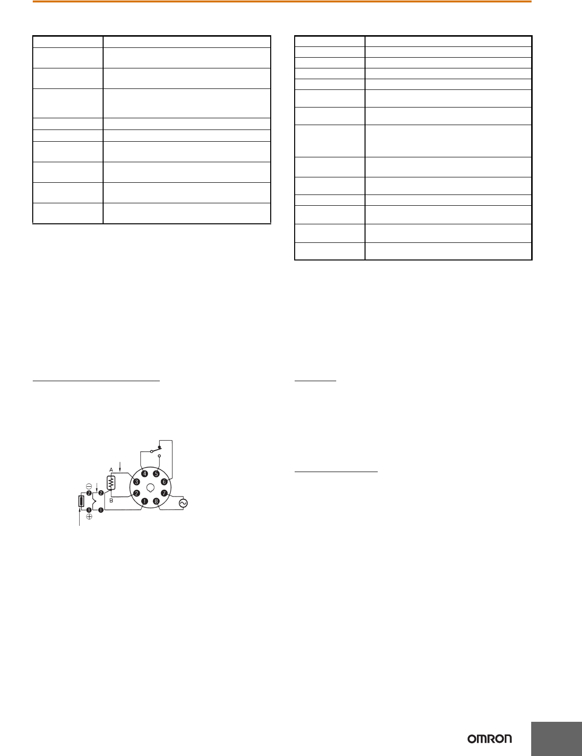
■ Connections
Connecting the Input
• Connect a thermocouple, the E52-THE@ Thermistor (replaceable
element) or a platinum resistance thermometer to terminals 1
(positive) and 2 (negative) on the E5C2 as shown in the following
illustration.
• On the E52-@@1D, the lead wires are thermocouple element wires,
making them difficult to solder because solder will not stick to them
easily. Remove the crimp terminal and polish the ends before
attempting to solder them.
Output
• If the load circuit is a heating control system, be sure to connect the
load to terminals 4 and 5. If the load circuit is a cooling control
system, be sure to connect the load to terminals 4 and 6.
• We recommend using an external relay to extend the electrical life
of internal relays when driving a large capacity load. This is
particularly important when the output relay is switched frequently
(e.g., with proportional control).
Power Supply
• If a single power supply is used for the E5C2 and the load, the
supply voltage of the power supply may vary greatly when the load
is open or closed if the capacity of the power supply is not large
enough. Make sure that the capacity of the power supply is large
enough so that the supply voltage range will be always from 90% to
110% of the rated supply voltage.
• The E5C2 operates at either 50 or 60 Hz.
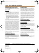
Supply voltage 100 to 240 VAC 50/60 Hz
Operating voltage
range
90% to 110% of rated supply voltage
Power
consumption
Approx. 3.6 VA
Input Thermocouple (with sensor burnout detection
circuit), platinum resistance thermometer, or
thermistor with replaceable element
Control method ON/OFF or proportional control
Setting method Analog setting
Indication
method
No indication
Control output Relay output: SPDT, 3 A at 250 VAC, resistive
load (switching capacity: 330 VA)
Ambient operat-
ing temperature
10C to 55C (with no icing or condensation)
Ambient operat-
ing humidity
45% to 85%
Setting accuracy 2% FS max.
Hysteresis Approx. 0.5% FS (fixed)
Proportional band 3% FS (fixed)
Control period Approx. 20 s
Reset range 5 1% FS min. (See note 1.)
Insulation
resistance
20 M min. (at 500 VDC)
Dielectric strength 2,000 VAC, 50/60 Hz for 1 min between charged termi-
nals and uncharged metallic parts
Vibration
resistance
Malfunction: 10 to 55 Hz, 0.15-mm single amplitude for
10 min each in X, Y, and Z directions
Destruction: 16.7 Hz, 2-mm double amplitude for 2 hrs
each in X, Y, and Z directions
Shock resistance
Malfunction: 147 m/s
2
, 3 times each in 6 directions
Destruction: 294 m/s
2
, 3 times each in 6 directions
Life expectancy Electrical: 100,000 operations min. (3 A at 110 VAC,
resistive load)
Weight Approx. 100 g (with flush-mounting adapter)
Degree of protection Front panel: IEC standard IP40 (See note 2.)
Terminals: IEC standard IP00
Applicable Socket P2CF-08 (order separately),
P3G-08 (order separately)
Applicable Protec-
tive Cover
Y92A-48B (order separately)
Thermocouple input
Thermistor with
replaceable element
Platinum resistance
thermometer input
Power supply
100 to 240 VAC
50/60 Hz
H12E-EN-03+E5C2+Datasheet.book Seite 3 Mittwoch, 8. Januar 2014 4:06 16