
Datasheet


11
E3Z
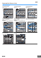
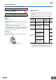
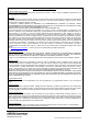
I/O Circuit Diagrams
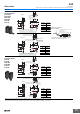
NPN Output
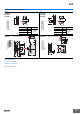
PNP Output
* Models numbers for Through-beam Sensors (E3Z-T@@) are for sets that include both the Emitter and Receiver.
The model number of the Emitter is expressed by adding "-L" to the set model number (example: E3Z-T61-L 2M), the model number of the Receiver, by adding "-D"
(example: E3Z-T61-D 2M.) Refer to Ordering Information to confirm model numbers for Emitter and Receivers.
Model*
Operation
mode
Timing charts
Operation
selector
Output circuit
E3Z-T61(K)
E3Z-T66
E3Z-T62
E3Z-T67
E3Z-T61A
E3Z-T66A
E3Z-R61(K)
E3Z-R66
E3Z-D61(K)
E3Z-D66
E3Z-D62(K)
E3Z-D67
E3Z-L61
E3Z-L66
E3Z-B61
E3Z-B66
E3Z-B62
E3Z-B67
E3Z-L63
E3Z-L68
Light-ON
L side
(LIGHT ON)
Dark-ON
D side
(DARK ON)
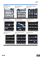
Model*
Operation
mode
Timing charts
Operation
selector
Output circuit
E3Z-T81(K)
E3Z-T86
E3Z-T82
E3Z-T87
E3Z-T81A
E3Z-T86A
E3Z-R81(K)
E3Z-R86
E3Z-D81(K)
E3Z-D86
E3Z-D82(K)
E3Z-D87
E3Z-L81
E3Z-L86
E3Z-B81
E3Z-B86
E3Z-B82
E3Z-B87
E3Z-L83
E3Z-L88
Light-ON
L side
(LIGHT ON)
Dark-ON
D side
(DARK ON)
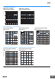
Incident light
No incident light
ON
OFF
ON
OFF
Operate
Reset
Operation
indicator
(orange)
(Between brown (1) and black (4) leads)
Output
transistor
Load
(e.g., relay)
Connector Pin Arrangement
Pin 2 is not used.
4
1
2
4
3
3
1
12 to 24 VDC
Br o w n
Bla c k
(Control
output)
Blue
100 mA
max.
Ope r ation
indicator
Stability
indicator
(Green)
(O r ange )
0 V
Z
D
Load
(Rel a y )
Photo -
elect r ic
Sensor
main
circuit
Through-beam Receivers, Retro-reflective Models,
Diffuse-reflective Models, Limited reflective Models.
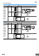
Incident light
No incident light
ON
OFF
ON
OFF
Operate
Reset
Operation
indicator
(orange)
(Between brown (1) and black (4) leads)
Output
transistor
Load
(e.g., relay)
1
2
4
3
3
1
Power
indicator
(orange)
Connector Pin Arrangement
Pins 2 and 4 are not used.
12 to
24 VDC
Brown
Blue
Photo-
electric
Sensor
main
circuit
Through-beam Emitter
Incident light
No incident light
ON
OFF
ON
OFF
Operate
Reset
Operation
indicator
(orange)
(Between blue (3) and black (4) leads)
Output
transistor
Load
(e.g., relay)
4
1
2
4
3
1
3
0 V
Z
D
Connector Pin Arrangement
Pin 2 is not used.
12 to 24 VDC
Brown
Black
(Control
output)
Blue
100 mA
max.
Operation
indicator
Stability
indicator
(Green)
(Orange)
Load
(Relay)
Photo-
electric
Sensor
main
circuit
Through-beam Receivers, Retro-reflective Models,
Diffuse-reflective Models, Limited reflective Models.
Incident light
No incident light
ON
OFF
ON
OFF
Operate
Reset
Operation
indicator
(orange)
(Between blue (3) and black (4) leads)
Output
transistor
Load
(e.g., relay)
1
2
4
3
3
1
Power
indicator
(orange)
Connector Pin Arrangement
Pins 2 and 4 are not used.
12 to 24 VDC
Brown
Blue
Photo-
electric
Sensor
Main
Circuit
Through-beam Emitter