
Datasheet
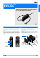


A-446 Advanced Photoelectric Sensors
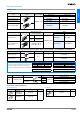
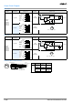
Output Circuit Diagram
NPN output
PNP output
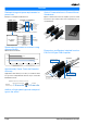
Connectors (Sensor I/O connectors)
Model
Operating status of
output transistor
Timing chart
Mode selec-
tion switch
Output circuit
E3X-NA11
E3X-NA6
E3X-NAG11
E3X-NA11F
E3X-NA11V
E3X-NA14V
Light ON
LON
(LIGHT ON)
Dark ON
DON
(DARK ON)
Model
Operating status of
output transistor
Timing chart
Mode selec-
tion switch
Output circuit
E3X-NA41
E3X-NA8
E3X-NAG41
E3X-NA41F
E3X-NA41V
E3X-NA44V
Light ON
LON
(LIGHT ON)
Dark ON
DON
(DARK ON)
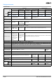
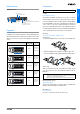
Incident
Interrupted
ON
OFF
ON
OFF
Operate
Reset
Operation
indicator
(orange)
(Between brown and black)
Output
transistor
Load
(Relay)
T
1
2
4
3
Black
Brown
Blue
Control output
Operation
indicator
(orange)
Main
circuit
Load
12 to 24 VDC
1
4
3
M8 Connector Pin Arrangement
Note: Pin 2 is open.
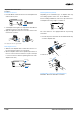
Incident
Interrupted
ON
OFF
ON
OFF
Operate
Reset
Operation
indicator
(orange)
(Between brown and black)
Output
transistor
Load
(Relay)
T
Incident
Interrupted
ON
OFF
ON
OFF
Operate
Reset
Operation
indicator
(orange)
(Between brown and black)
Output
transistor
Load
(Relay)
T
1
2
4
3
Black
Brown
Blue
Control output
Operation
indicator
(orange)
Main
circuit
Load
12 to 24 VDC
1
4
3
M8 Connector Pin Arrangement
Note: Pin 2 is open.
Incident
Interrupted
ON
OFF
ON
OFF
Operate
Reset
Operation
indicator
(orange)
(Between brown and black)
Output
transistor
Load
(Relay)
T
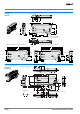
2
4
1
3
1
2
3
4
Brown
White
Blue
Black
Color of
cable conductors
Termination No.
XS3F-M421-402-A
XS3F-M421-405-A
XS3F-M422-402-A
XS3F-M422-405-A
Note: Pin 2 is not used.
Class
Wire, outer
jacket color
Connector
pin No.
Application
For DC
Brown A
Power
supply (+V)
White B -
Blue C
Power
supply (0 V)
Black D Output