
Datasheet

E2E/E2EQ NEXT Series
22
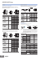
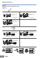
I/O Circuit Diagrams
DC 2-Wire Models
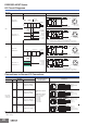
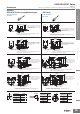
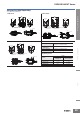
Connections to Sensor I/O Connectors
Note: Different from Proximity Sensor wire colors.
* If the XS5W-D421-@81-X or XS5W-D421-@81-F Connector which has a socket and plug on the cable ends is connected to the Sensor, this part
will be a plug.
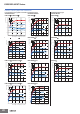
Operation
mode
Model Timing Chart Output circuit
NO
E2E-X@D1@
E2EQ-X@D1@
E2E-X@D1@-T
E2EQ-X@D1@-T
NC
E2E-X@D2@
E2EQ-X@D2@
E2E-X@D2@-T
E2EQ-X@D2@-T
Proximity Sensor
Sensor I/O Connector
model number
Connections
Type Polarity
Operation
mode
Model
DC 2-wire
(Smartclick
Connector)
Yes NO
E2E-X@D1@-M1TGJ
E2EQ-X@D1@-M1TGJ
No NC
E2E-X@D2@-M1TGJ
E2EQ-X@D2@-M1TGJ
Yes NO
E2E-X@D1@-M1TGJ-T
E2EQ-X@D1@-M1TGJ-T
No NC
E2E-X@D2@-M1TGJ-T
E2EQ-X@D2@-M1TGJ-T
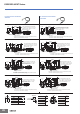
(%)
80
0
100
Sensing
object
Rated
sensing
distance
Stable
sensing area
Non-
sensing
area
Unstable
sensing
area
Set position
Proximity
Sensor
ON
OFF
ON
OFF
ON
OFF
Setting
indicator
(green)
Operation
indicator
(orange)
Control
output
0 V
1
4
Proximity
sensor
main
circuit
Note: The load can be connected to either the +V or 0 V side.
Load
10 to 30 VDC
Connector Pin
Arrangement
Note: Pins 2 and 3
are not used.
Brown
Blue
Load
Note1. The load can be connected to either the +V or 0 V side.
4
3
Proximity
sensor
main
circuit
Note: Pins 1 and 2
are not used.
Connector Pin
Arrangement
2.
The E2E@-X@D1@(-M1TGJ)-T has no polarity. There is no need to be
concerned about the polarity of brown and blue wires, or pins 3 and 4.
10 to 30 VDC (0V)
0V (10 to 30 VDC)
Brown
Blue
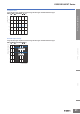
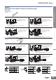
0
(%)
100
Sensing
object
Rated
sensing
distance
Sensing area
Non-sensing
area
Proximity
Sensor
Operation
indicator
(orange)
Control
output
ON
OFF
ON
OFF
0 V
1
2
Proximity
sensor
main
circuit
Note: The load can be connected to either the +V or 0 V side.
Load
10 to 30 VDC
Connector Pin
Arrangement
Note: Pins 3 and 4
are not used.
Brown
Blue
Load
Note1. The load can be connected to either the +V or 0 V side.
1
2
Proximity
sensor
main
circuit
Note: Pins 3 and 4
are not used.
Connector Pin
Arrangement
2.
The E2E@-X@D1@(-M1TGJ)-T has no polarity. There is no need to be
concerned about the polarity of brown and blue wires, or pins 1 and 2.
10 to 30 VDC (0V)
0V (10 to 30 VDC)
Brown
Blue
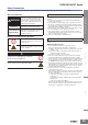
XS5F-D421-@80-X
or
XS5F-D421-@80-F
The box @ is replaced
by the cable length.
C: 1-m cable
D: 2-m cable
E: 3-m cable
G: 5-m cable
J: 10-m cable
XS5F
4
3
2
1
4
3
2
1
E2E/E2EQ NEXT Series
Blue (not connected)
Black
(−)
Brown (+)
White (not connected)
Main
circuit
*
4
3
2
1
4
3
2
1
Blue (not connected)
Black (not connected)
Brown
(+)
White (−)
Main
circuit
XS5FE2E/E2EQ NEXT Series
*
4
3
2
1
4
3
2
1
Main
circuit
Blue (+) (−)
Black (−) (+)
XS5FE2E/E2EQ NEXT Series
Brown (not connected)
White (not connected)
*
4
3
2
1
4
3
2
1
Main
circuit
White (−)(+)
Blue (not connected)
Brown (+)(−)
Black (not connected)
XS5FE2E/E2EQ NEXT Series
*