
Datasheet


E2E
11
● Mounting
Tightening Force
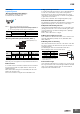
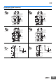
〈Mounting threaded models (E2E-S@)〉
Do not tighten the nut with excessive force.
A washer must be used with the nut.
Note: 1.
Only use the provided nut and toothed washer.
Risk of changes in the sensing distance and damage if a different
material is used. If you lose the nut or washer, purchase an optional nut
set.
2. The following strengths assume washers are being used.
Note: Only use the provided nut.
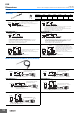
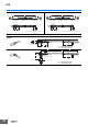
〈Mounting unthreaded cylindrical models (E2E-C@)〉
* Excluding the operation indicator area.
When using a set screw, tighten it to the torque indicated in the table above.
● Oil resistance
In accordance with our oil resistance standard, we test oil resistance
based on water insoluble oil (complies with test oil based on JIS
C0920, Appendix 1).
When water soluble cutting oil is used, durability varies due to the
dilution ratio and other factors.
Please test oil resistance using the actual oil that will be used.
● High-speed responsiveness
To obtain a better high-speed response, it is recommended that you
use the sensor at about 50% of the possible sensing distance.
A high-speed response may not be obtained with some sensing
object surfaces, materials, and shapes, or when the sensing distance
is greater than the set distance.
For the effects of materials, refer to Engineering Data on page 7.
● Protective Stainless-steel Spiral Tube
The spiral tube is in a fixed state and is intended to provide protection
against wire breakage due to shock from tools or other objects.
● Repeated cable bending tolerance
If you require repeated bending tolerance, use a sensor with a robot
(bending-resistant) cable or use a Connector Model together with a
connector cable that is specified for bending tolerance. (Example:
XS3F-M321-@@@-R)
Refer to Sensor I/O Connector on page 5.
● Block type mounting accessories
Due to differences in dimensional tolerances, these cannot be used
with older small diameter proximity sensors. (E2E-CR6@, E2E-
CR8@, E2E-C1@)
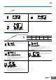
● Bending radius for mounting
If the cable is bent from its base, the resin on the surface of the cable
may peel off, however, this will not affect the protective structure or
sensing performance.
Avoid bending the cable at less than 10 mm from the base.
When bending the cable, refer to the table below.
● Total Cable Length
If you extend the cable length, use a conductor cross section of 0.14
mm
2
or greater and do not exceed a total length of 200 m for standard
cables or robot (bending-resistant) cables. It is assumed that an
independent metal conduit will be used.
Size M4 M5
Item Shielded Unshielded Shielded Unshielded
Tr 0.8 N·m 1 N·m
Size 3 dia. 4 dia.
5.4
dia.
6.5 dia.
Item
Shielded Unshielded Shielded Unshielded Shielded Shielded Unshielded
L *
9 to 21
mm
15 to 27
mm
8 to 21
mm
14 to 27
mm
8 to 21
mm
12 to 26 mm
Torque 0.2 N·m max. 0.4 N·m max.
Tr
Dimpled end of set screw (M3)
(Screw not provided)
L
R
10 mm
Sensor
* For a robot (bending-resistant) cable,
multiply the bending radius in the
above table by 1.7.
Cable diameter Bending radius*
3 dia., M4 7 mm
4 dia., 5.4 dia., M5 9 mm
6.5 dia. 12 mm