
Datasheet


E2E
9
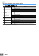
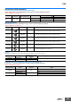
I/O Circuit Diagrams
Connection to I/O Connector (Connector Models, Pre-wired Connector Models)
Operation
mode
Output
specifications
Model Timing chart Output circuit
NO
NPN open-
collector
output
E2E-@@@@
-@@-C1
NC
E2E-@@@@
-@@-C2
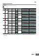
NO
PNP open-
collector
output
E2E-@@@@
-@@-B1
NC
E2E-@@@@
-@@-B2
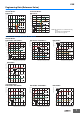
Sensing
object
Rated
sensing
distance
(%)
100 0
Sensing area
Non-sensing area
Proximity
Sensor
ON
OFF
ON
OFF
Operation
indicator
(yellow)
Control
output
Load
Brown
1
Black
Blue
Proximity
Sensor
main
circuit
10 to 30 VDC
31
4
Connector pin arrangement
M8
4
3
(%)
100 0
ON
OFF
ON
OFF
Proximity
Sensor
Sensing area
Non-sensing area
Sensing
object
Rated
sensing
distance
Operation
indicator
(yellow)
Control
output
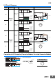
Sensing
object
Rated
sensing
distance
(%)
100 0
Sensing area
Non-sensing area
Proximity
Sensor
ON
OFF
ON
OFF
Operation
indicator
(yellow)
Control
output
Load
10 to 30 VDC
Connector pin arrangement
M8
Proximity
Sensor
main
circuit
Brown
1
Black
4
Blue
3
31
4
(%)
100 0
ON
OFF
ON
OFF
Proximity
Sensor
Sensing area
Non-sensing area
Sensing
object
Rated
sensing
distance
Operation
indicator
(yellow)
Control
output
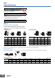
1
4
3
1
4
3
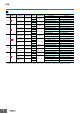
NPN
XS3F-M32@-3@@-R
1
4
3
1
4
3
PNP
02: 2 m
05: 5 m
1: Straight
2: Right-angle
Brown
Black
Blue
Brown
Black
Blue
Sensor I/O Connector
I/O connector cable,
connector arrangement diagram
31
4