
Datasheet


D4NL
7
Connections
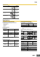
Internal Circuit Diagram
Indicator
Solenoid
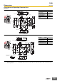
Circuit Connection Example
Connection Example for D4NL-@F@@-B
• Terminals 12 and 41 are connected internally. When connecting
inputs to safety circuits, use terminals 11 and 42. (GS-ET-19).
• Connect terminals 21 and 22 and terminals 51 and 52 in series
when using as safety-circuit inputs (redundancy circuit for
terminals 11 and 12 and terminals 41 and 42 below). Connect the
terminals individually when using as auxiliary-circuit inputs (e.g.,
terminals 21 and 22 for safety-door open/closed monitoring and
terminals 51 and 52 for monitoring the lock status).
• In the following connection example, terminals 21 and 22 and
terminals 51 and 52 are used as auxiliary-circuit inputs.
• Direct opening contacts used as safety-circuit inputs are indicated
with the mark. Terminals 11 and 42, and terminals 21 and 22
have direct opening contacts.
• Connect the indicators in parallel to the auxiliary circuits or
terminals E1 and E2 (D4NL-@@@A-B, -@@@G-B, -@@@B-B, and
-@@@H-B only).
Connecting to contacts with direct opening mechanisms may result
in short-circuit current flowing if the indicator is destroyed, possibly
resulting in incorrect equipment operation.
• Do not switch circuits for two or more standard loads at the same
time. Doing so may adversely affect insulation performance.
• DC solenoids have polarity. Confirm terminal polarity before wiring.
D
R
R
LED
Z
10 to 115 VAC/VDC
Constant-current diode
E1 (+)
E2 (−)
24 VDC
E1 (+)
E2 (−)
110 VAC/230 VAC
42
11
21
33
E1 (+)
O1 O2
12 41
5
1
52
22
34
E2 (−)
Indicator
(Orange)
Safety
circuit
Auxiliary
circuit
Auxiliary
circuit
Auxiliary
circuit