
Datasheet


D4NL
14
Application Examples
Note:
The above PL is only the evaluation result of the example. The PL must be evaluated in an actual application by the customer after confirming the usage conditions.
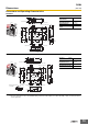
●Application Overview
• The stop signal is sent to the motor controller.
• The power supply to the motor M is turned OFF after OFF-delay time.
• The lock release signal enables the guard to be opened.
• The S1 and S2 monitor the guard, and the power supply to the motor M is kept OFF while the guard is opened.
• The power supply to the motor M is turned ON again when the reset switch S3 is pressed while the guard is closed and locked.
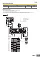
PL/safety category Model Stop category Reset
PLd/3 equivalent
Guard Lock Safety-door Switch
D4NL-@A@A-@, -@A@B-@, -@A@C-@ (Mechanical Lock Type)
Safety Relay Unit G9SA-321-T@ (24 VAC/VDC)
1 Manual
TH
SA
S2
OPEN
S4
KM1
KM2
42
41
12
11
PLC
PLC
54
53
34
33
A1 A2
T11 T12 T31 T32
13 23 33 43 53 61
1
2
3
4
5
6
JP
K3
3
4
2
5
K4
K1
K2
K1
K1
PE
T21 T23 T22
A B
14 24 34
KM1 KM2
KM1
KM2
M
44 54 62
K2
K2
6
K3
1
a
b
OffDelay
Timer
Control
Circuit
K4
a
b
Stop signal
Guard
KM1
KM2
S3
S1
Lock release signal
Stop
instruction
Motor controller
Feedback loop
S1: Safety Limit Switch
with direct opening mechanism
(D4B-N, D4N, D4F)
S2: Guard Lock Safety-door Switch
S3: Reset switch
S4: Lock release switch
KM1 and KM2: Magnetic Contactor
M: 3-phase motor
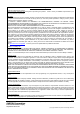
Timing Chart
Motor rotation
OFF-delay time
Limit switch S1
Reset switch
S3
K1 and K2
(NC)
K1 and K2
(NO)
K3 and K4
(NC)
K3 and K4
(NO)
KM1 and KM2
(NC)
KM1 and KM2
(NO)
Operation
instruction
Lock release
signal
S4
Stop signal
Guard opens
Guard can be opened
Guard Lock
Safety-door
Switch S2