
Datasheet


D4B-@N
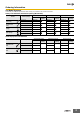
10
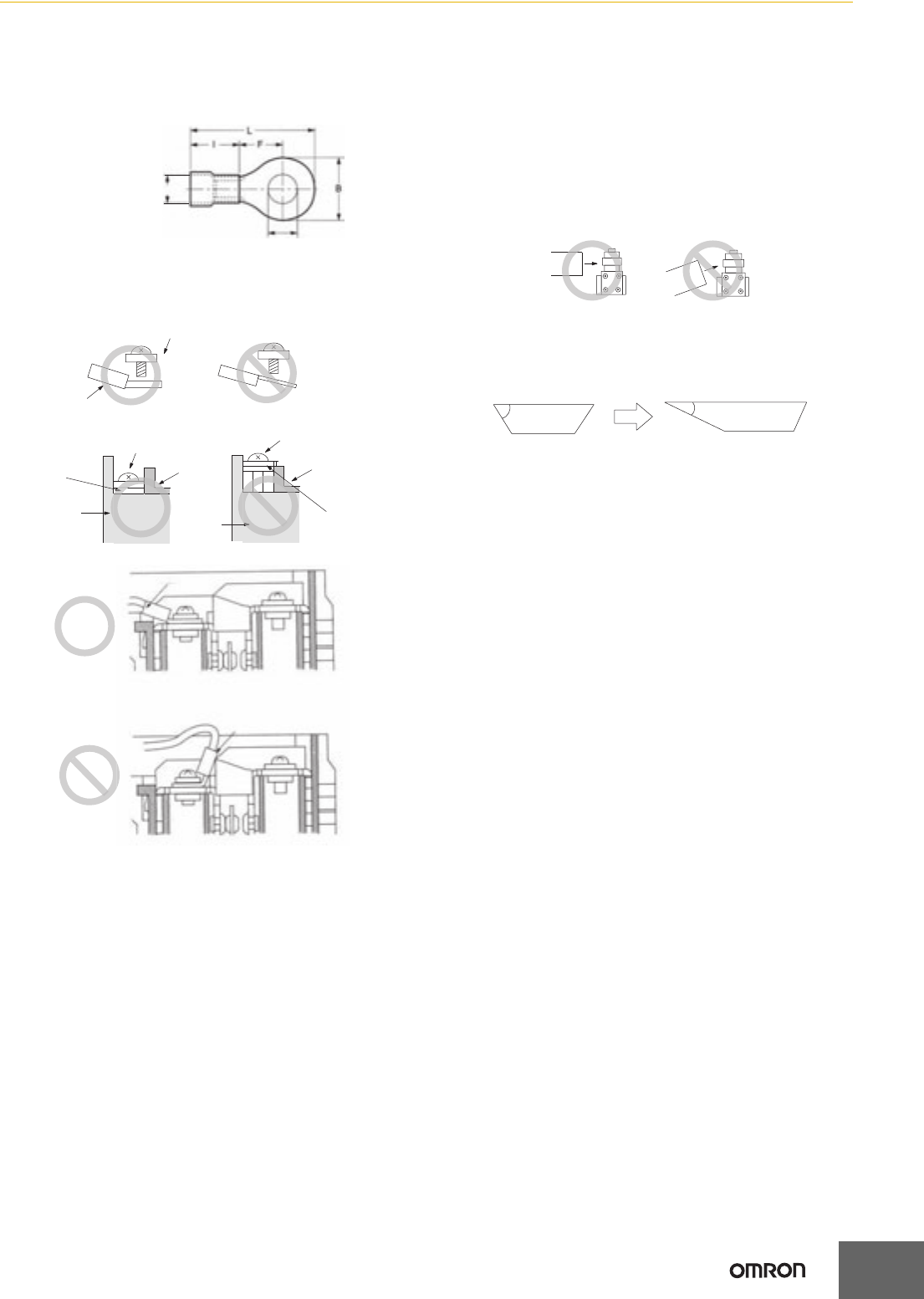
Wiring
Do not connect the bare lead wires directly to the terminals but be
sure to connect each of them by using an insulation tube and M3.5
round crimp terminals and tighten each terminal screw within the
specified torque range.
The proper lead wire is 20 to 14 AWG (0.5 to 2.5 mm
2
) in size.
Make sure that all crimp terminals come into contact with the casing
or cover as shown below, otherwise the cover may not be mounted
properly or the D4B-@N may malfunction.
Conduit Opening
• Make sure that each connector is tightened within the specified
torque range.
The casing may be damaged if the connector is tightened
excessively.
• Use an OMRON SC-series Connector (sold separately) that is
suited to the cable in diameter.
Others
• The load for the actuator (roller) of the Switch must be imposed on
the actuator in the horizontal direction, otherwise the actuator or
the rotating axis may be deformed or damaged.
•
When using a long lever model, the D4B-
@@
16N or D4B-
@@
17N,
the
Switch may telegraph. To avoid telegraphing, take the following
precautions.
1. Set the lever to operate in one direction.
2. Modify the rear end of the dog to an angle of 15° to 30° as
shown below or to a secondary-degree curve.
3. Modify the circuit so as not to detect the wrong operating
signals.
D dia.
dz dia.
dz dia.: 3.7 mm
D dia.: 4.5 mm
B: 7.0 mm
L: 20.2 mm
F: 7.7 mm
l: 9.0 mm
Casing
Cover
Terminal screw
Crimp terminal
Terminal screw
Casing
Terminal screw
Cover
Crimp terminal
Correct
Correct
Incorrect
Incorrect
Crimp
terminal
Crimp terminal
Crimp terminal
Correct
Incorrect
Dog
Dog
Correct Incorrect
θ
θ
θ ≥ 30°
15° ≤ θ ≤ 30°