
Datasheet


CP1L
14
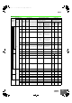
I/O Specifications for CPU Units
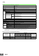
■ Input Specifications
*1. High-speed counter inputs, interrupt inputs, and quick-response inputs can also be used as normal inputs.
*2. The bits that can be used depend on the model of CPU Unit.
*3. The response time is the hardware delay value. The delay set in the PLC Setup (0 to 32 ms, default: 8 ms) must be added to this value.
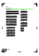
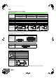
● High-speed Counter Function Input Specifications
Input bits: CIO 0.00 to CIO 0.03
● Interrupt Input Counter Mode
Input bits: CIO 0.04 to CIO 0.09
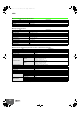
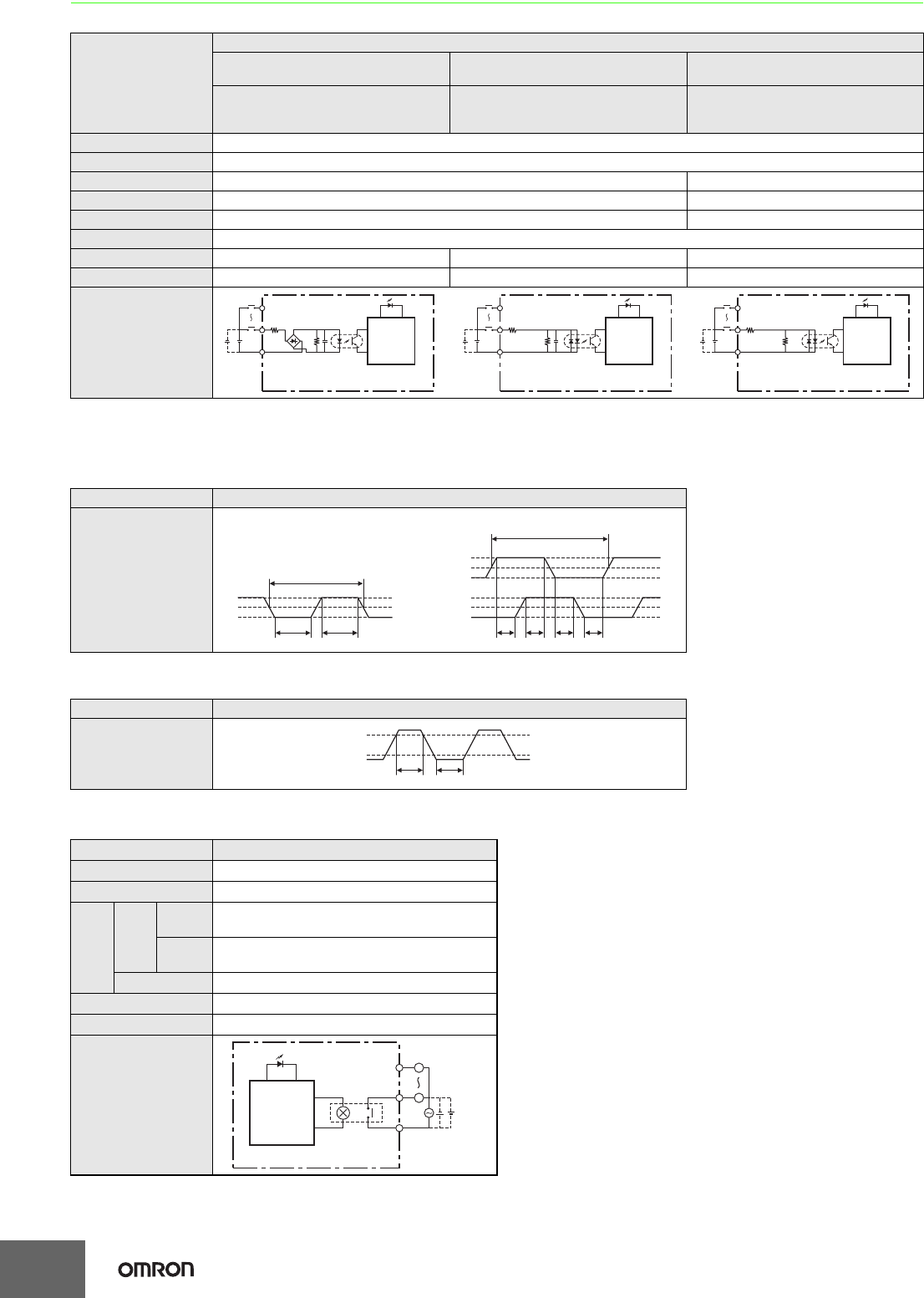
■ Output Specifications
● CPU Units with Relay Outputs
Note: There are restrictions in the power supply voltage and output load current imposed by the ambient temperature for CPU Units with DC power.
Refer to the CP1L CPU Unit Operation Manual (Cat. No. W462) or the CP Series CP1L-EL/EM CPU Unit Operation Manual (Cat. No. W516).
ITEM
Specifications
High-speed counter inputs
(phases A and B) *1
Interrupt inputs and
quick-response inputs *1
Normal inputs
CIO 0.00 to CIO 0.03 CIO 0.04 to CIO 0.09 *2
CIO 0.10 to CIO 0.11,
CIO 1.00 to CIO 1.11, and
CIO 2.00 to 2.11 *2
Input voltage 24 VDC +10%/–15%
Applicable sensors 2-wire sensors or 3-wire sensors
Input impedance 3.0 kΩ 4.7 kΩ
Input current 7.5 mA typical 5 mA typical
ON voltage 17.0 VDC min. 14.4 VDC min.
OFF voltage/current 1 mA max. at 5.0 VDC
ON delay *3 2.5 μs max. 50 μs max. 1 ms max.
OFF delay *3 2.5 μs max. 50 μs max. 1 ms max.
Circuit configuration
Item Specifications
ON/OFF delay
Item Specifications
ON/OFF delay
Item Specifications
Max. switching capacity 2 A, 250 VAC (cosφ = 1), 2 A, 24 VDC 4 A/common)
Min. switching capacity 5 VDC, 10 mA
Ser-
vice
life of
relay
Elec-
trical
Resis-
tive load
100,000 operations (24 VDC)
Induc-
tive load
48,000 operations (250 VAC, cosφ = 0.4)
Mechanical 20,000,000 operations
ON delay 15 ms max.
OFF delay 15 ms max.
Circuit configuration
Internal
circuits
IN
IN
COM
3.0 kΩ
1000 pF
4.3 kΩ
Input LED
Internal
circuits
IN
IN
COM
3.0 kΩ
1000 pF
910 Ω
Input LED
Internal
circuits
IN
IN
COM
4.7 kΩ
750 Ω
Input LED
10.0 μs min.
ON
OFF
90%
10%
50%
2.5 μs min.2.5 μs min.
ON
OFF
ON
OFF
Phase A
Phase A
90%
10%
50%
90%
10%
50%
20.0 μs min.
T
1,T2,T3,T4 : 2.5 μs min
T
1 T2 T3 T4
• Pulse plus direction input mode
• Increment mode
• Up/down input mode
• Differential phase input mode
90%
10%
OFF
ON
50 μs min. 50 μs min.
Internal circuits
L
L
OUT
OUT
COM
Output LED
Maximum
250 VAC: 2 A,
24 VDC: 2 A
CP1L.fm 14 ページ 2012年3月19日 月曜日 午後1時18分