
Datasheet


230 Programmable Controllers
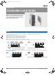
CJ1W-CLK21-V1
Controller Link Units
Simpler Controller Link Wiring, Startup, and
Construction Provides Larger-capacity Data
Links, Greater Flexibility in Area Control, and
Supports Multiple Sub-networks
The data link capacity is 20,000 words per node. Allocate both Data
Link Area 1 and Area 2 in the same area. Connect up to 8 Units under
a single CPU Unit. (Unit Ver. 1.2 only)
Using Wired Controller Link Units together with Repeater Units allows
network configurations for essentially any application, including T-bran-
ching, long-distance applications, applications with up to 62 nodes, or
applications with optical sections in a wired network. Models are also
available that enable changes in configurations and automatic 1:N
communications while data links are active.
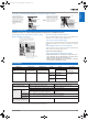
Huge increase in amount of data that can be collected from devices.
Number of data link send/receive words (total of Area 1 and Area 2) for a single Controller Link Unit increased from 12,000 to 20,000 words.
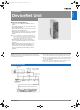
The same Memory Area can be used for the Data Link Areas. For example, Data Link Areas 1 and 2 can be both allocated
and managed in EM Bank 0.
Function
The increasing amount of data required from each device
(e.g., tracking data, inspection history data, error monitoring
data) makes the previous data link limit of 12,000 words per
node (total send and receive words in Area 1 and Area 2 for
manually set data links) insufficient for many applications.
New CS/CJ-series Controller Link Units (Wired/Optical Ring) can handle up to 20,000
send/receive data link words (total of Area 1 and Area 2) for a single node. This
enables more data to be collected from each device.
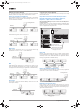
(To host)
12,000 words max.
Before
If only
I could transfer
inspection data for
each workpiece.
If only I could collect
more data from each
device (PLC).
If only I could
increase the error
monitoring data.
I have to use
SEND/RECV
instructions to transfer
the rest of the data.
(To host)
Up to 20,000 words
Using Controller Link Unit Ver. 1.2
Now
Controller Link
Controller Link
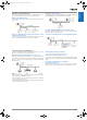
Area 1 and Area 2 had to be allocated in separate Memory Areas for user-set
data links. Therefore, allocating all data links in the EM Area was not possible.
New CS/CJ-series Controller Link Units (Wired/Optical Ring Units) enable both Areas 1
and 2 to be allocated in the same Memory Area when using user-set data links. Provided
addresses do not overlap, the same Memory Area can be used, making area control
easier.
Area 1:
CIO Area
Before
Area 2:
EM Area
Both Areas
1 and 2:
EM Area
Now
Y201-EN2-03.book Seite 230 Donnerstag, 30. März 2006 1:52 13