
Datasheet


162 Programmable Controllers
Providing Effective Solutions by Integrating Sequence Control and Loop Control into the Same Basic
Functionality of the CJ Series
Overview
An engine for controlling analog quantities (e.g., temperature, pressure, flowrate) is built into the same CPU Unit as the engine for executing se-
quence control, delivering high-speed sequence control and high-speed, advanced analog quantity control in a single Unit.
Features
• Program graphically by pasting function blocks for PID control, square root calculations, or other functions in a window and then connect them
with the mouse.
• More than 70 types of function blocks are provided, including Bank Selector and Split Converter (for heating and cooling control), supporting a
wide array of control methods from basic PID control to cascade control and feed-forward control.
• Function blocks enable a control cycle speed of up to 10 ms. A range of control methods are supported from detailed flowrate control and pres-
sure control to high-speed temperature control.
• The CX-Process Tool can be used to open the tuning window and change parameters while monitoring PVs, SPs, and MVs.
• The Face Plate Auto-builder for NS (order separately) can be used to automatically create touch panel adjustment windows, including control
windows, tuning windows, and segment program parameter setting windows, from function block data.
Programming Example
Function Specifications
CPU Element (Sequence Control)
Loop Controller Element (Loop Control)
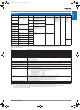
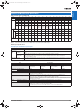
CJ1G-CPU@@P (Loop-control CPU Units) Specifications
Name I/O bits Program capacity DM words EM words Model
Loop-control CPU Unit 1,280 bits 60K steps 32K words 32K words × 3 banks
E0_00000 to E2_32767
CJ1G-CPU45P
30K steps 32K words × 1 bank
E0_00000 to E0_32767
CJ1G-CPU44P
960 bits 20K steps CJ1G-CPU43P
10K steps CJ1G-CPU42P
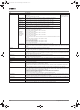
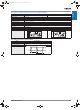
Item Model CJ1G-CPU42P CJ1G-CPU43P CJ1G-CPU44P CJ1G-CPU45P
Operation method Function block method
Operation cycle 0.01, 0.02, 0.05, 0.1, 0.2, 0.5, 1, or 2 s (default: 1 s)
Can be set for each function block.
Number
of func-
tion
blocks
Analog
operations
Control and operation
blocks
50 blocks max. 300 blocks max.
Sequence con-
trol
Step ladder program
blocks
20 blocks max.
2,000 commands total
200 blocks max. 4,000 commands total
I/O blocks Field terminal blocks 30 blocks max. 40 blocks max.
User link tables 2,400 data items max.
Batch allocation HMI function, allocated 1 EM Area bank
System Common block Single block
Method for creating and transferring function
blocks
Created using CX-Process Tool (order separately) and transferred to Loop Controller.
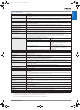
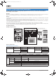
CX-Process Tool (Software for Personal Computer)
A Combine function blocks and connect graphically using the mouse.
SP
Face Plate Auto-Builder for NS
C Touch panel windows are automatically generated.
Segment program
parameter setting window
Tuning window
NS-series PT
Loop-control CPU Unit
Serial or
Ethernet
Control window
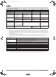
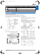
TIC
Input
CH1
Output
CH1
Time
RSP
PV
MV
Temperature
input
Heater
output
Analog
Input
Unit
Analog
Output
Unit
Loop-control CPU Unit
CH1
CH2
CH3
CH4
CH1
CH2
CH3
CH4
PV
RSP
MV
Analog Output
Field Terminal
Analog Input
Field Terminal
Y1
Segment
Program
Basic PID
B Adjust PID and other para-
meters in the tuning window.
Segment Program
Example: Program Control
Y201-EN2-03.book Seite 162 Donnerstag, 30. März 2006 1:52 13