
Datasheet


160 Programmable Controllers
Built-in Output Specifications
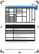
Position Control and Speed Control
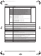
Variable-duty Pulse Outputs (PWM)
Note: CJ1M CPU Unit Ver. 2.0 or later only. (0% to 100%, set in 1% units for Pre-Ver. 2.0 CPU Units.)
Hardware Specifications
Input Specifications
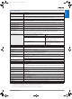
Input Circuit Configuration
Item Specifications
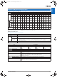
Output frequency 1 Hz to 100 kHz (1-Hz units from 1 to 100 Hz, 10-Hz units from 100 Hz to 4 kHz, and
100-Hz units from 4 to 100 kHz)
Frequency acceleration and
deceleration rates
Set in 1 Hz units for acceleration/deceleration rates from 1 Hz to 2 kHz (every 4 ms). The acceleration and decel-
eration rates can be set separately only with PLS2(887).
Changing SVs during instruc-
tion execution
The target frequency, acceleration/deceleration rate, and target position can be changed. Changes to the target
frequency and acceleration/deceleration rate must be made at constant speed.
Pulse output method CW/CCW inputs or Pulse + direction inputs
Number of output pulses Relative coordinates: 00000000 to 7FFFFFFF hex (Each direction accelerating or decelerating: 2,147,483,647)
Absolute coordinates: 80000000 to 7FFFFFFF hex (−2,147,483,648 to 2,147,483,647)
Instruction used for origin
searches and returns
ORIGIN SEARCH (ORG(889)): Origin search and origin return operations according to set parameters
Instructions used for position
and speed control
PULSE OUTPUT (PLS2(887): Trapezoidal output control with separate acceleration and deceleration rate
SET PULSES (PULS(886)): Setting the number of pulses for pulse output
SPEED OUTPUT ((SPED(885): Pulse output without acceleration or deceleration (Number of pulses must be set
in advance with PULS(886) for position control.)
ACCELERATION CONTROL (ACC(888)): Changes frequency or pulse output with acceleration and deceleration
MODE CONTROL (INI(880)): Stopping pulse output
Pulse output PV's storage loca-
tion
The following Auxiliary Area words contain the pulse output PVs:
Pulse output 0: A277 (leftmost 4 digits) and A276 (rightmost 4 digits)
Pulse output 1: A279 (leftmost 4 digits) and A278 (rightmost 4 digits)
The PVs are refreshed during regular I/O refreshing. PVs can be read to user-specified words with the PRV(881)
instruction.
Item Specifications
Duty ratio 0% to 100%, set in 0.1% units (See note.)
Frequency 0.1 Hz to 999.9 Hz, Set in 0.1 Hz units.
Instruction PULSE WITH VARIABLE DUTY RATIO (PWM(891)): Sets duty ratio and outputs pulses.
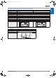
Item Specifications
Number of inputs 10 inputs
Input method 24-V DC inputs or line driver (wiring changed to select)
Input voltage specifications 24 V DC Line driver
Terminals IN0 to IN5 IN6 to IN9 IN0 to IN5 IN6 to IN9
Input voltage 20.4 to 26.4 V DC RS-422A or RS-422 line driver (conforming to
AM26LS31), Power supply voltage of 5 V ±5%
Input impedance 3.6 kΩ 4.0 kΩ --- ---
Input current (typical) 6.2 mA 4.1 mA 13 mA 10 mA
Minimum ON voltage 17.4 V DC/3 mA min. --- ---
Maximum OFF voltage 5.0 V DC/1 mA max.
Response
speed (for gen-
eral-purpose in-
puts)
ON response
time
Default setting: 8 ms max. (The input time constant can be set to 0 ms, 0.5 ms, 1 ms, 2 ms, 4 ms, 8 ms, 16 ms,
or 32 ms in the PLC Setup.)
OFF response
time
Default setting: 8 ms max. (The input time constant can be set to 0 ms, 0.5 ms, 1 ms, 2 ms, 4 ms, 8 ms, 16 ms,
or 32 ms in the PLC Setup.)
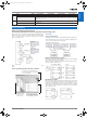
Item Specification
Input IN0 to IN5 IN6 to IN9
Circuit configuration
24 V
LD+
0 V/LD−
3.6 kΩ
100 Ω
750 Ω
100 Ω
1,000 pF
Internal circuits
24 V
LD+
0 V/LD−
4.0 kΩ
1.5 kΩ
100 Ω
100 Ω
1,000 pF
Internal circuits
Y201-EN2-03.book Seite 160 Donnerstag, 30. März 2006 1:52 13