
Datasheet


CJ1 series CPU Units 159
Programmable
Controllers
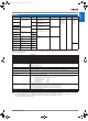
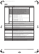
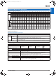
Data Area Allocations for Built-in I/O
Note: 1. CJ1M-CPU21 CPU Units have one PWM output only and do not have PWM output 1.
Built-in Input Specifications
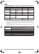
Interrupt Inputs and Quick-response Inputs
High-speed Counter Inputs
Additional CJ1M-CPU21/22/23 Specifications
I/O Code IN0 IN1 IN2 IN3 IN4 IN5 IN6 IN7 IN8 IN9 OUT1 OUT2 OUT3 OUT4 OUT5 OUT6
Address CIO 2960 CIO 2961
Bit 00 01 02 03 04 05 06 07 08 09 00 01 02 03 04 05
Inputs General-
purpose
inputs
General-
purpose
input 0
General-
purpose
input 1
General-
purpose
input 2
General-
purpose
input 3
General-
purpose
input 4
General-
purpose
input 5
General-pur-
pose input 6
General-pur-
pose input 7
General-pur-
pose input 8
General-pur-
pose input 9
--- --- --- --- --- ---
Interrupt
inputs
Interrupt
input 0
Interrupt
input 1
Interrupt
input 2
Interrupt
input 3
--- --- --- --- --- --- --- --- --- --- --- ---
Quick-
response
inputs
Quick-
response
input 0
Quick-
response
input 1
Quick-
response
input 2
Quick-
response
input 3
--- --- --- --- --- --- --- --- --- --- --- ---
High-
speed
counters
--- --- High-
speed
counter 1
(phase-Z/
reset)
High-
speed
counter 0
(phase-Z/
reset)
--- --- High-speed
counter 1
(phase-A,
increment, or
count input)
High-speed
counter 1
(phase-B,
decrement,
or direction
input)
High-speed
counter 0
(phase-A,
increment, or
count input)
High-speed
counter 0
(phase-B,
decrement,
or direction
input)
--- --- --- --- --- ---
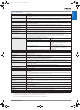
Out-
puts
General-purpose
outputs
--- --- --- --- --- --- --- --- --- --- General-
purpose
output 0
General-
purpose
output 1
General-
purpose
output 2
General-
purpose
output 3
General-
purpose
output 4
General-
purpose
output 5
Pulse
out-
puts
CW/CCW
outputs
--- --- --- --- --- --- --- --- --- --- Pulse out-
put 0
(CW)
Pulse out-
put 0
(CCW)
Pulse out-
put 1
(CW)
Pulse out-
put 1
(CCW)
--- ---
Pulse +
direction
outputs
--- --- --- --- --- --- --- --- --- --- Pulse out-
put 0
(pulse)
Pulse out-
put 1
(pulse)
Pulse out-
put 0
(direction)
Pulse out-
put 1
(direction)
--- ---
Variable
duty ratio
outputs
--- --- --- --- --- --- --- --- --- --- --- --- --- --- PWM(891)
output 0
PWM(891)
output 1
(See note.)
Origin search Origin
search 0
(Origin
Input Sig-
nal)
Origin
search 0
(Origin
Proximity
Input Sig-
nal)
Origin
search 1
(Origin
Input Sig-
nal)
Origin
search 1
(Origin
Proximity
Input Sig-
nal)
Origin
search 0
(Position-
ing Com-
pleted
Signal)
Origin
search 1
(Position-
ing Com-
pleted
Signal)
--- --- --- --- --- --- --- --- Origin
search 0
(Error
Counter
Reset Out-
put)
Origin
search 1
(Error
Counter
Reset Out-
put)
Item Specification
No. of interrupt inputs/quick-re-
sponse inputs
4 total
Input inter-
rupts
Direct (Input Inter-
rupt) Mode
Execution of an interrupt task is started at the interrupt input's rising or falling edge. Interrupt numbers 140 to 143 are used
(fixed).
Response time from meeting input condition to start of interrupt task execution: 93 μs min.
High-speed
Counter Mode
Rising or falling edges of the interrupt are counted using either an incrementing or decrementing counter, and an interrupt
task is started when the input count reaches the set value. Interrupt numbers 140 to 143 are used (fixed).
I/O response frequency: 1 kHz
Quick-response inputs Signals that are shorted than the cycle time (30 μs min.) can be read and treated the same as signals that are one for more
than one cycle time.
Item Specification
Number of high-speed counters 2 (High-speed counters 0 and 1)
Pulse input mode (Selected in PLC Setup) Differential phase inputs
(phase-A, phase-B, and
phase-Z input)
Up/down inputs
(up inputs, down inputs,
reset inputs)
Pulse + direction inputs
(pulse inputs, direction in-
puts, reset inputs)
Increment inputs
(increment inputs, reset
inputs)
Response fre-
quency
Line-driver inputs 50 kHz 100 kHz 100 kHz 100 kHz
24-V DC inputs 30 kHz 60 kHz 60 kHz 60 kHz
Counting mode Linear mode or Ring mode (Select in the PLC Setup.)
Count value Linear mode: 80000000 to 7FFFFFFF hex
Ring mode: 00000000 to Ring SV
(The Ring SV is set in the PLC Setup and the setting range is 00000001 to FFFFFFFF hex.)
High-speed counter PV storage locations High-speed counter 0: A271 (leftmost 4 digits) and A270 (rightmost 4 digits)
High-speed counter 1: A273 (leftmost 4 digits) and A272 (rightmost 4 digits)
Target value comparison interrupts or range comparison interrupts can be executed based on these PVs. The
PVs are refreshed in the overseeing processes at the beginning of each cycle. Use the PRV(881) instruction
to read the most recent PVs.
Control
method
Target value comparison Up to 48 target values and corresponding interrupt task numbers can be registered.
Range comparison Up to 8 ranges can be registered, with an upper limit, lower limit, and interrupt task number for each.
Counter reset method Phase-Z + Software reset: Counter is reset when phase-Z input goes ON while Reset Bit is ON.
Software reset: Counter is reset when Reset Bit goes ON.
Reset Bits: High-speed Counter 0 Reset Bit is A53100, Counter 1 Reset Bit is A53101.
Y201-EN2-03.book Seite 159 Donnerstag, 30. März 2006 1:52 13