
Datasheet


CJ1 series CPU Units 157
Programmable
Controllers
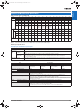
Function Specifications
Note: 1. Supported for CPU Unit Ver. 3.0 or later only.
2. Supported for CPU Unit Ver. 2.0 or later only (Three-level communications are supported for Pre-Ver. 2.0 CPU Units.)
3. Supported for CX-Programmer Ver. 5.0 and CPU Unit Ver. 3.0 or later only.
4. Use a Replacement Battery that is within two years of its date of manufacture.
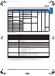
Item Specification
Constant cycle time 1 to 32,000 ms (Unit: 1 ms)
Note: With the CJ1G/H-CPU@@H, using the Parallel Processing Mode will create a constant cycle time for program
execution.
Cycle time monitoring Possible (Unit stops operating if cycle is too long): 1 to 40,000 ms (Unit: 10 ms)
Note: When the Parallel Processing Mode is used for the CJ1G/H-CPU@@H, the program execution cycle is monitored.
Also, a fatal error will occur in the CPU Unit if the peripheral servicing time exceeds 2 s.
I/O refreshing Cyclic refreshing, immediate refreshing, refreshing by IORF(097).
Special refreshing for CPU Bus Units Data links for Control Link Units, remote I/O communications for DeviceNet Units, and other special data for CPU Bus Units
is refreshed at the following times.
During I/O refresh period or when CPU BUS UNIT I/O REFRESH (DLNK) instruction is executed.
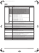
I/O memory holding when
changing operating modes
Depends on ON/OFF status of IOM Hold Bit in Auxiliary Area.
Load OFF All outputs on Output Units can be turned OFF when the CPU Unit is RUN, MONITOR, or PROGRAM mode.
Input time constant setting Time constants can be set for inputs from CJ-series Basic I/O Units. The time constant can be increased to reduce influence
of noise and chattering or it can be decreased to detect shorter pulses on inputs.
Operating mode setting at
power-up
Possible (By default, the CPU Unit will start in RUN mode if a Programming Console is not connected.)
Built-in flash memory · Always stores (automatically backs up/restores) the user program and parameter area data (PLC Setup, etc.)
· When downloading projects from the CX-Programmer Ver. 5.0 or later, symbol table files (including CX-Programmer
symbol names and I/O comments), comment files (CX-Programmer rung comments and annotations),
and program index files (CX-Programmer section names, section comments, and program comments) are stored in
the flash memory’s internal Comment Memory (See note 1).
Memory Card functions Automatically reading programs (autoboot) from the Memory
Card when the power is turned ON.
Possible
Program replacement during PLC operation Possible
Memory Card storage data User program: Program file format
PLC Setup and other parameters: Data file format
I/O memory: Data file format (binary), text format,
CSV format
CPU Bus Unit data: Special format
Memory Card read/write method User program instructions, Programming Devices
(including CX-Programmer and Programming Console),
Host Link computers, AR Area control bits, easy
backup operation
Filing Memory Card data and EM (Extended Data Memory) Area can be handled as files.
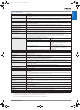
Debugging Force-set/reset, differential monitoring, data tracing (scheduled, each cycle, or when instruction is executed)
Online editing One or more program blocks in user programs can be overwritten when CPU Unit is in PROGRAM or MONITOR mode.
This function is not available for block programming areas. With the CX-Programmer, more than one program block can be
edited at the same time.
Program protection Overwrite protection:Set using DIP switch.
Copy protection: Password set using CX-Programmer.
Error check User-defined errors (i.e., user can define fatal errors and non-fatal errors)
The FPD(269) instruction can be used to check execution time and logic of each programming block.
Error status can be simulated with the FAL and FALS instructions.
Error log Up to 20 errors are stored in error log. Information includes error code, error details, and time error occurred.
The system can be set so that user-defined FAL errors are not stored in the error log.
Serial communications Built-in peripheral port: Programming Device (e.g., CX-Programmer or Programming Console), Host Links, NT Links
Built-in RS-232C port: Programming Device (e.g., CX-Programmer), Host Links, no-protocol communications, NT Links,
Serial PLC Links (CJ1M only)
Serial Communications Unit (sold separately): Protocol macros, Host Links, NT Links
Clock Provided on all models. Accuracy: ± 1.5 min/mo. at 25°C (accuracy varies with the temperature)
Note: Used to store time when power is turned ON and when errors occur.
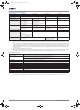
Power OFF detection time 10 to 25 ms (not fixed)
Power OFF detection delay time 0 to 10 ms (user-defined, default: 0 ms)
Memory protection Held Areas: Holding bits, user program, Data Memory, Extended Data Memory, and status of counter Completion Flags and
present values.
Note: If IOM Hold Bit in Auxiliary Area is turned ON, and PLC Setup is set to maintain IOM Hold Bit status when power to
PLC is turned ON, contents of CIO Area, Work Area, part of Auxiliary Area, timer Completion Flag and PVs, Index
Registers, and Data Registers will be saved for up to 20 days.
Sending commands to a Host Link
computer
FINS commands can be sent to a computer connected via Host Link System by executing Network Communications
Instructions from PLC.
Remote programming and monitoring Host Link communications can be used for remote programming and remote monitoring through a Controller Link System or
Ethernet network.
Eight-level communications
(See note 2.)
Host Link communications can be used for remote programming and remote monitoring from devices on networks up to
eight levels away (Controller Link Network, Ethernet Network, or other network). CPU Ver. 2.0 or higher. Older CPUs support
up to three levels.
Storing comments in CPU Unit I/O comments can be stored in Memory Cards, EM file memory, or (Ver. 3.0 and higher) in the comment memory
(See note 3.) integrated in the CPU.
Program check Program checks are performed for items such as no END instruction and instruction errors. CX-Programmer can also be
used to check programs.
Control output signals RUN output: The internal contacts will turn ON (close) while the CPU Unit is operating (CJ1W-PA205R).
Battery life 5 years at 25 °C (The battery life depends on the ambient operating temperature; 0.75 years min. for CJ1H/G, 1.5 years min.
for CJ1M) (See note 4.)
Self-diagnostics CPU errors (watchdog timer), I/O bus errors, memory errors, and battery errors
Other functions Storage of number of times power has been interrupted. (Stored in A514.)
Y201-EN2-03.book Seite 157 Donnerstag, 30. März 2006 1:52 13